Category: Assignment-11-Automaton

rippling

Isabella & Alex

So essentially, this motor-controlled automata was a flop (I severely lack motor skills ha). There was too much focus put into the structure of the actual moving parts and building them, which led to an overall automata that was unable to be moved by a motor due to the heaviness of parts and the original placement of these parts. Our original idea of how the motor would be placed on the large dowel did not work, unless we were to change the entire holding structure of the piece. So due to that, it had to be cranked by hand instead. The original concept was to create this moving structure that resembled the rippling of a wave acting as a visualization of an object touching the ground or some other surface.

DSC05544
DSC05541

The Finger

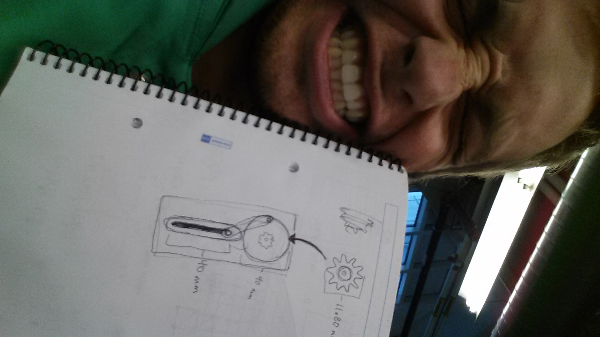
So the final form of this project represents how I feel about this project Actually never mind, by the end of the project, due to a litany of technical difficulties and having to scrap what I thought I was coding and reinstall the entire arduino driver, this is actually pretty much how I felt about it:IMG_2329

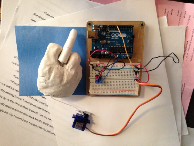
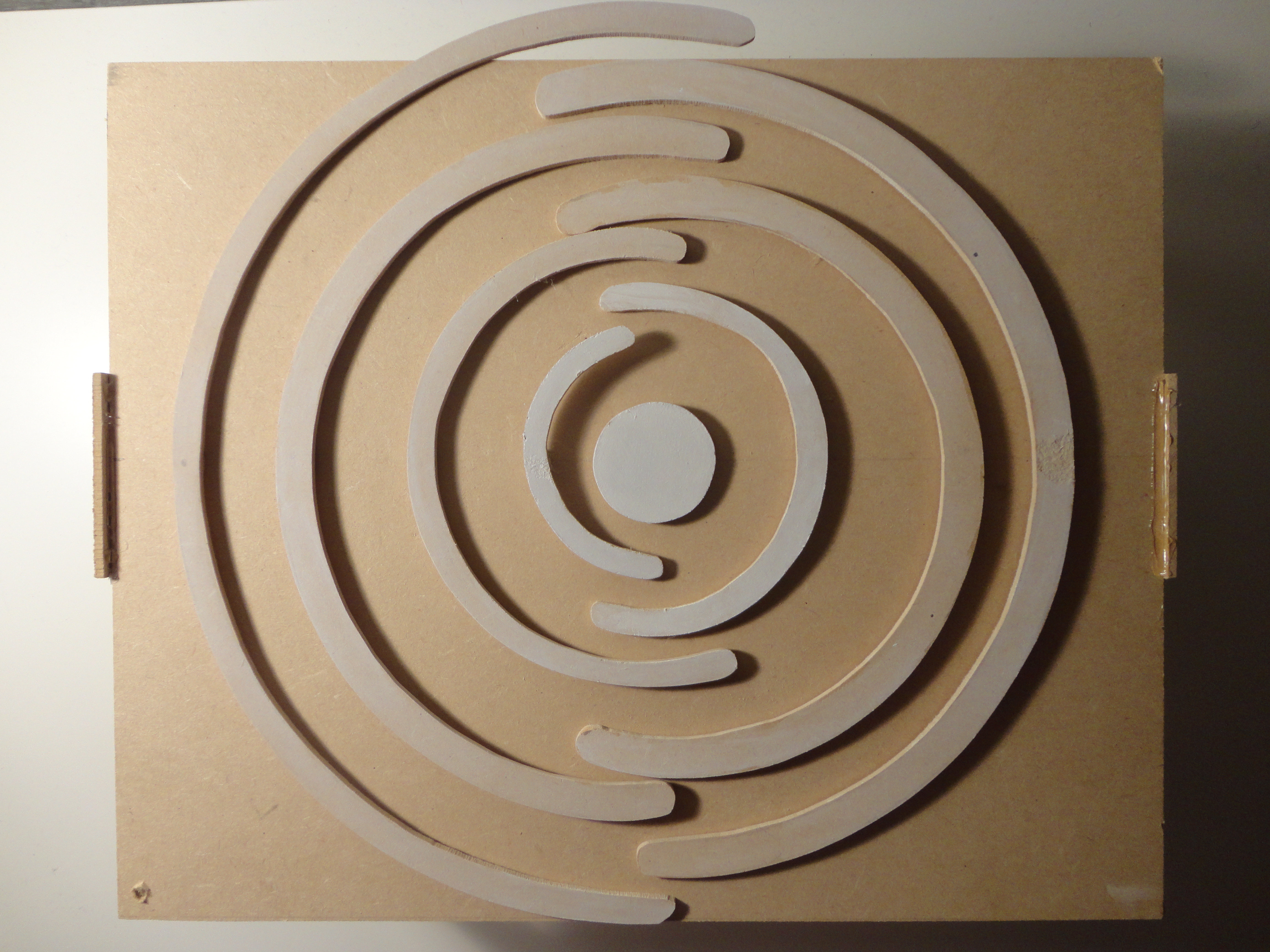
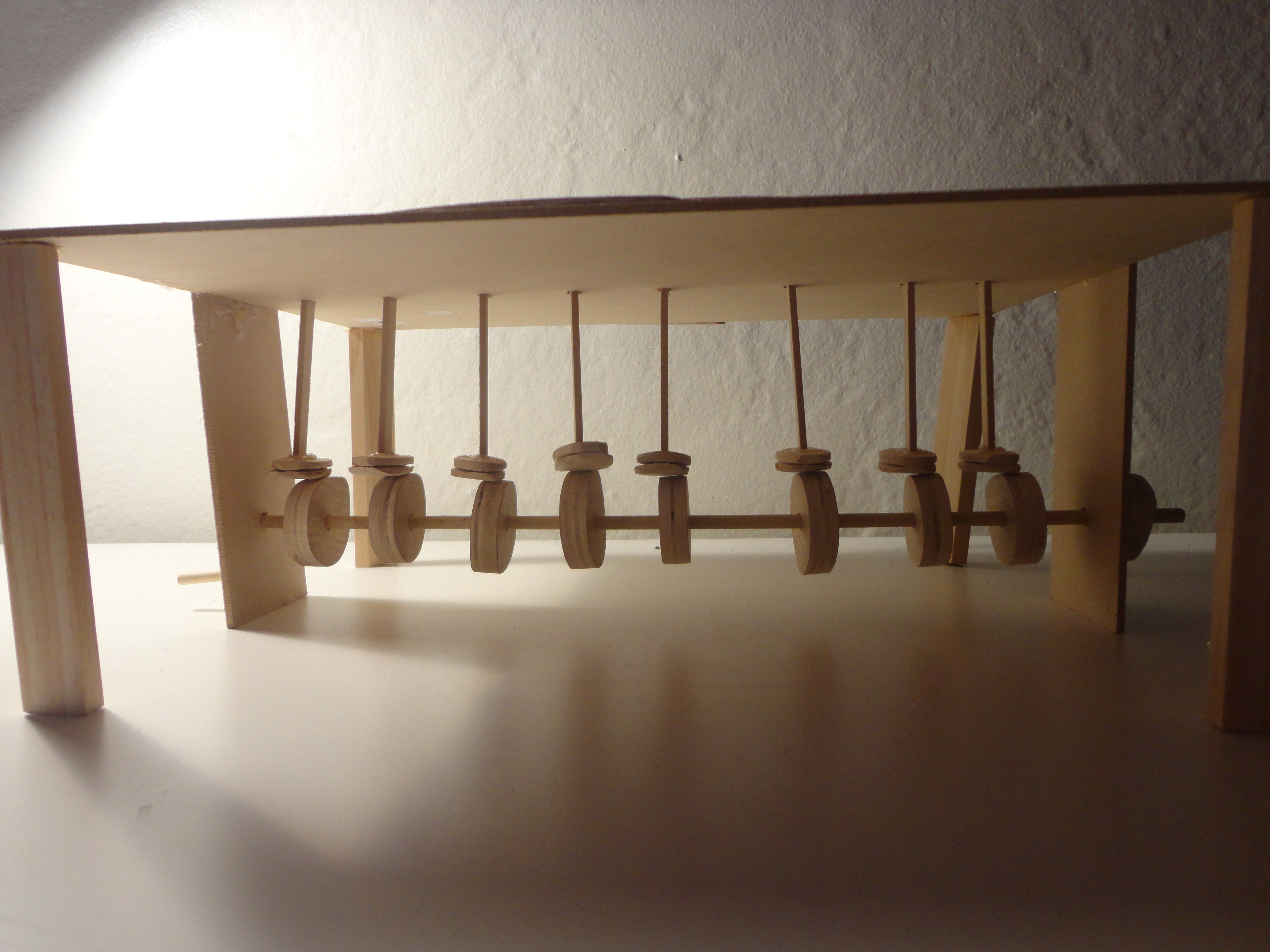
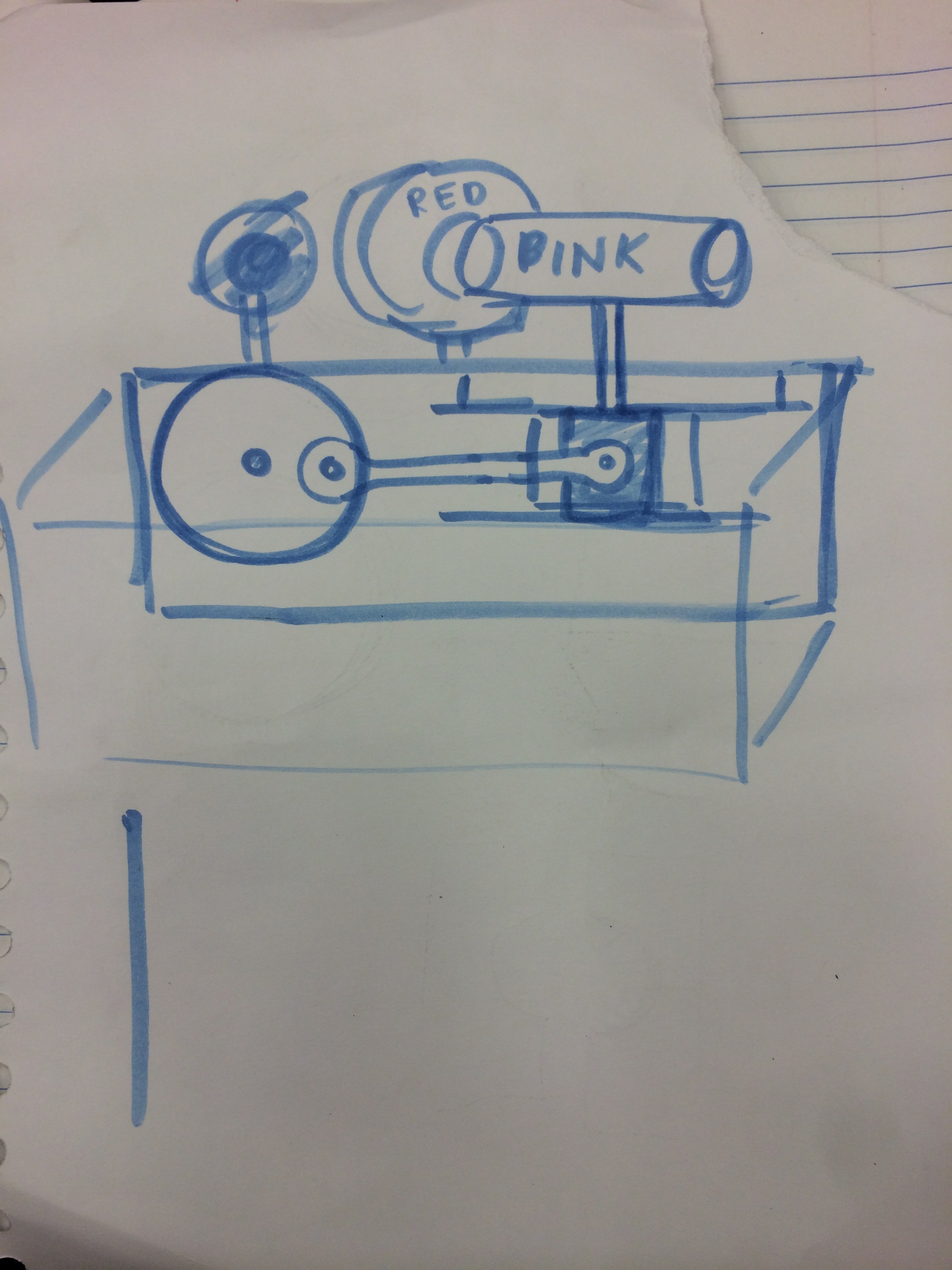
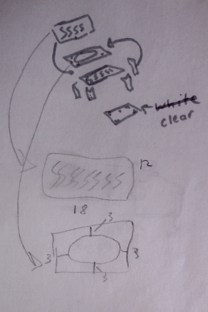
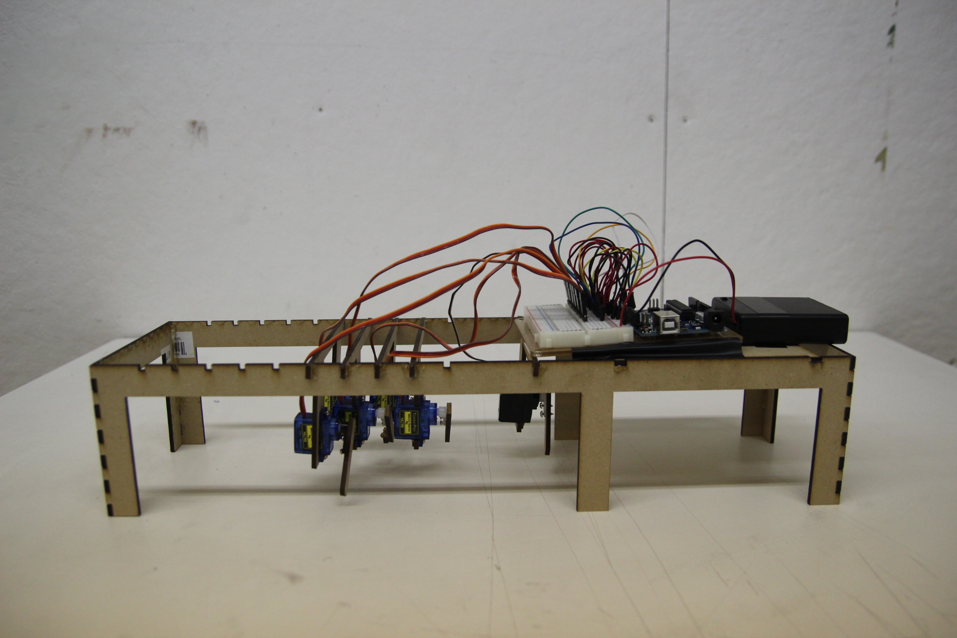
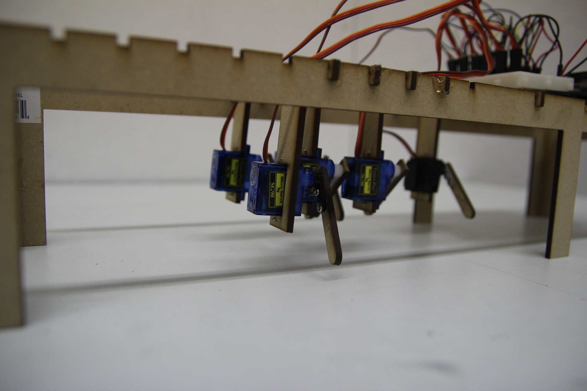
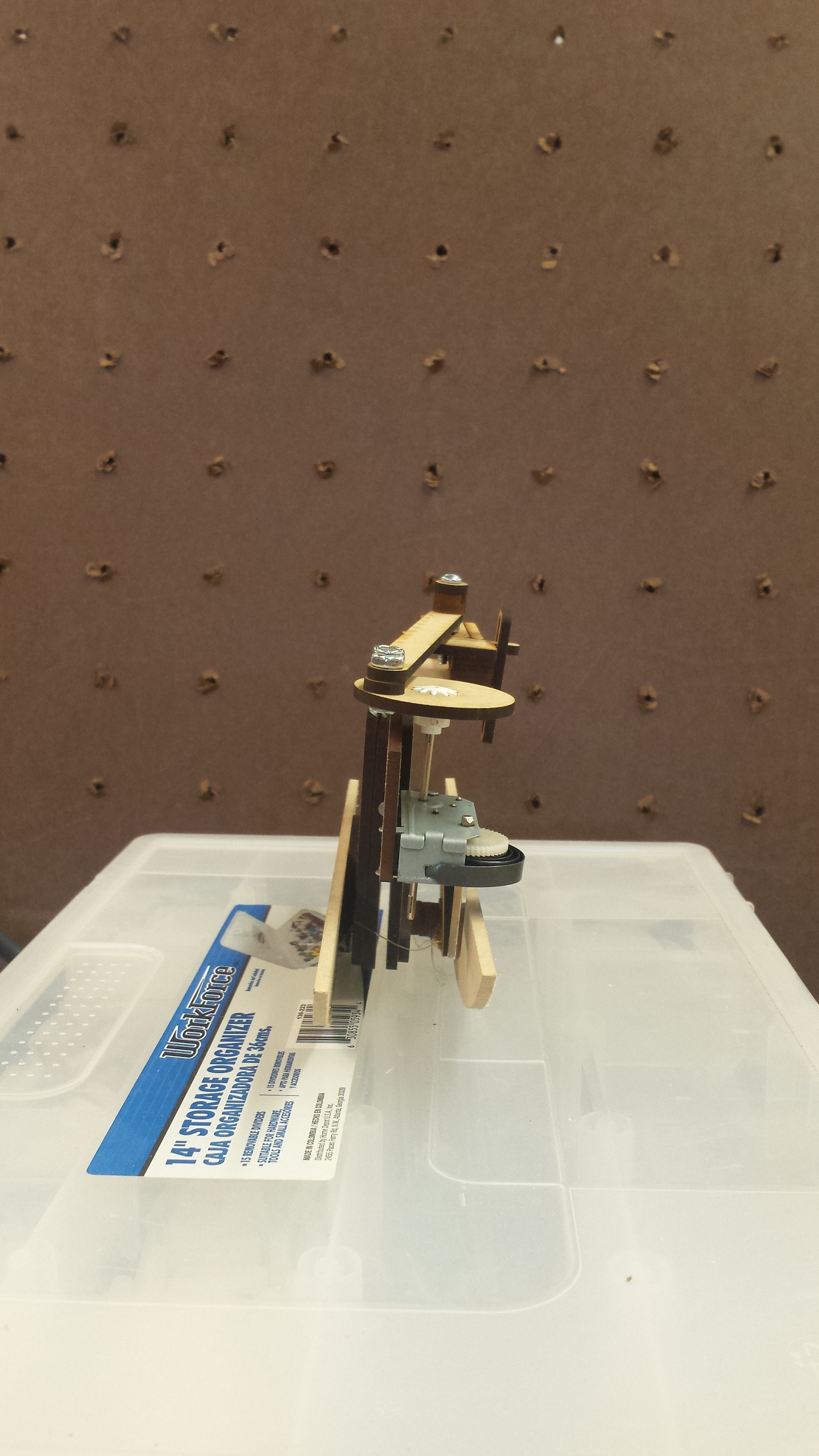
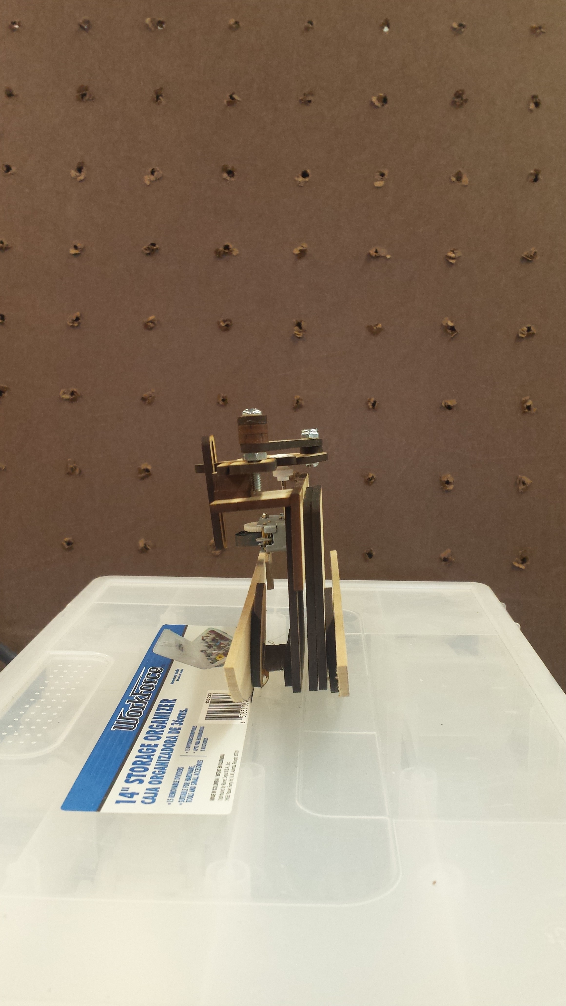
In any case, the original conception of this project was that I wanted to make a hand. Just in general. Hands are expressive and they move in ways that seem pretty basic but aren’t. Initially I thought I was going to do something ridiculously complicated with like sixteen itty bitty gears that would replicate finger joints, just to prove that I could make a hand. Once I’d gotten that far it was too late to come up with a different concept, so I thought, “Okay, I’m making a hand. How can I make it interesting and/or amusing?”

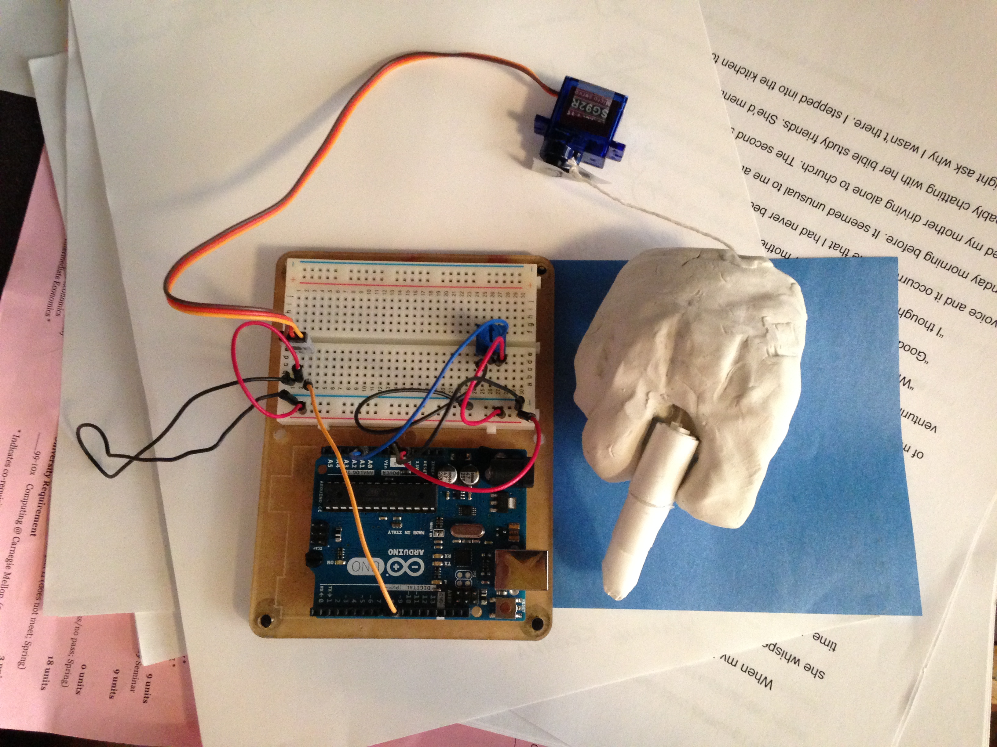
And so this happened. Basically it’s a horribly lumpy little clay hand about the size of a ten-year-old’s, which gives the middle finger to its audience when you twist a potentiometer. There’s that saying, something like “it takes 4o something muscles to frown and only 4 to smile” and I don’t know how many it takes to flip someone the bird. I don’t know how many more muscles it is to turn a dial on a potentiometer, but I bet it’s more than just sticking up the middle finger yourself. Essentially, this is a machine that says that you’re putting some real effort into telling someone “fuck you.”

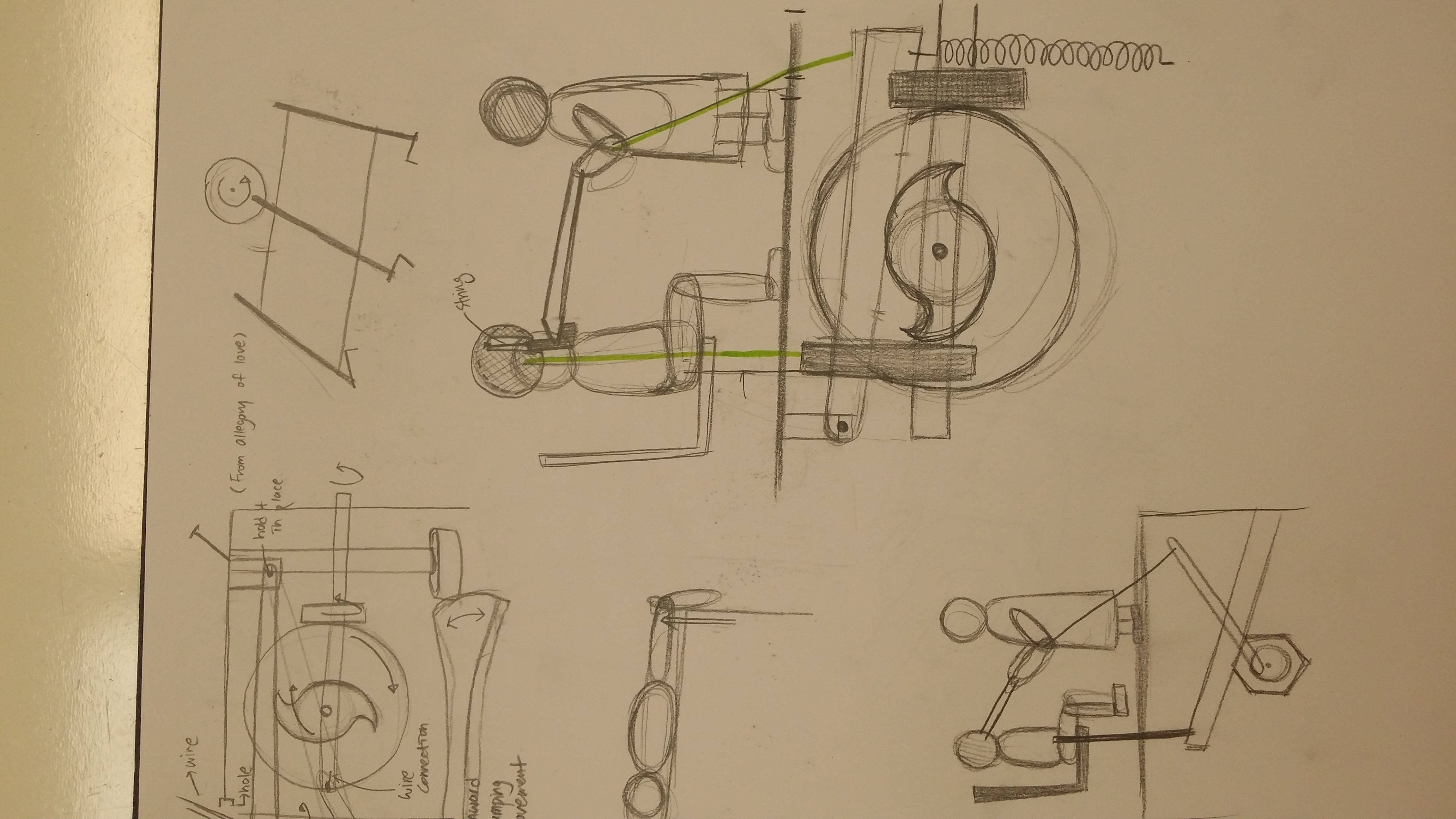
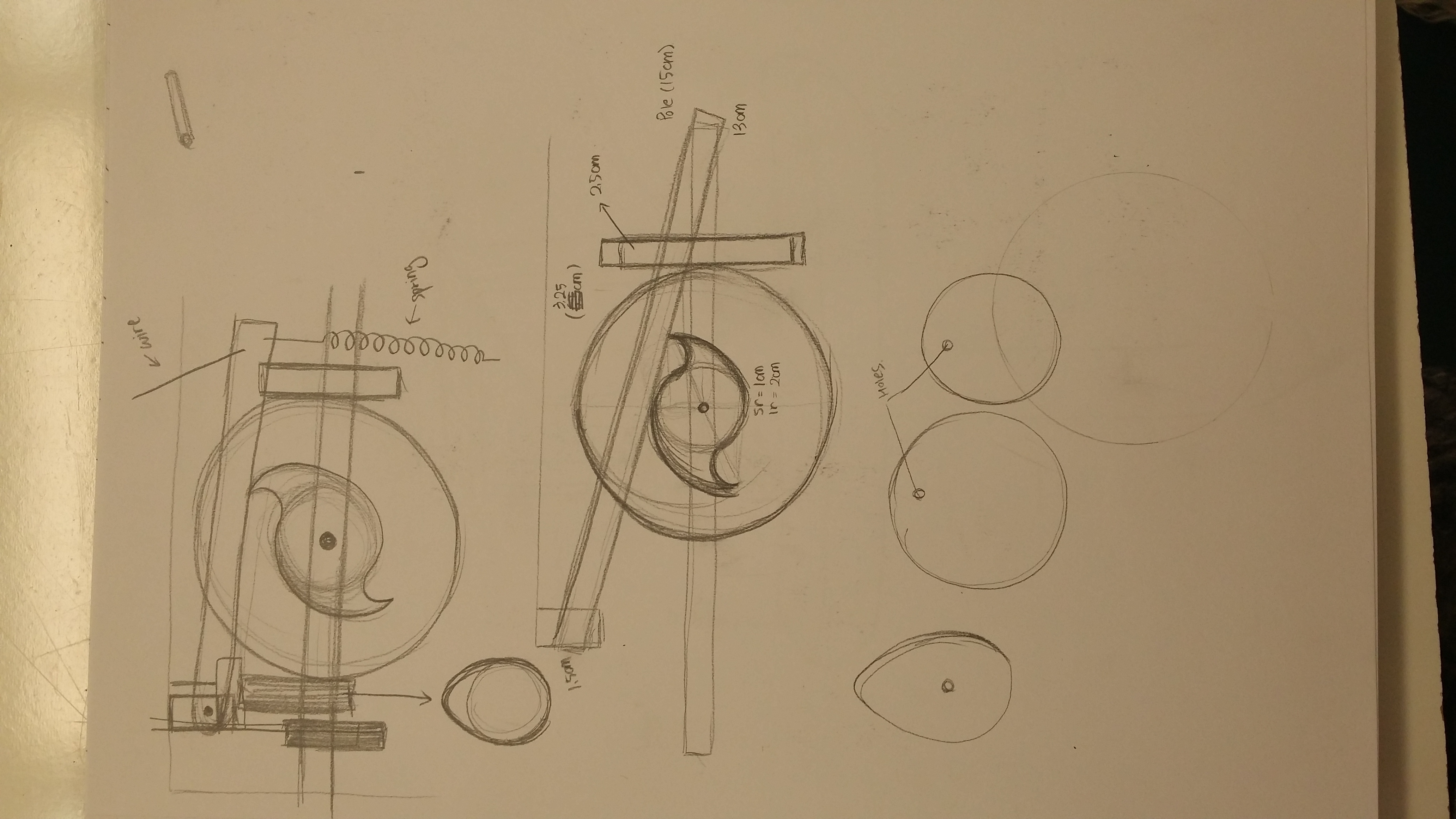
(Sketches are coming I promise)
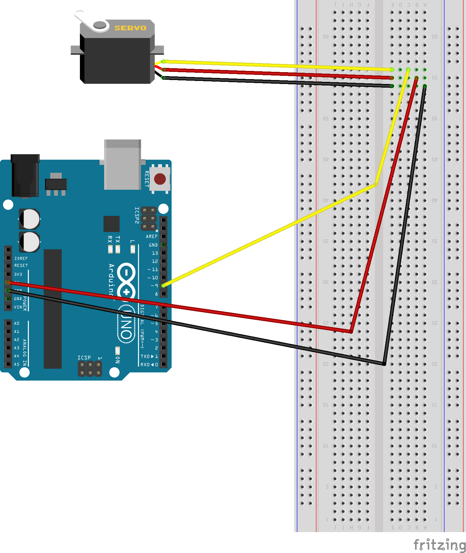
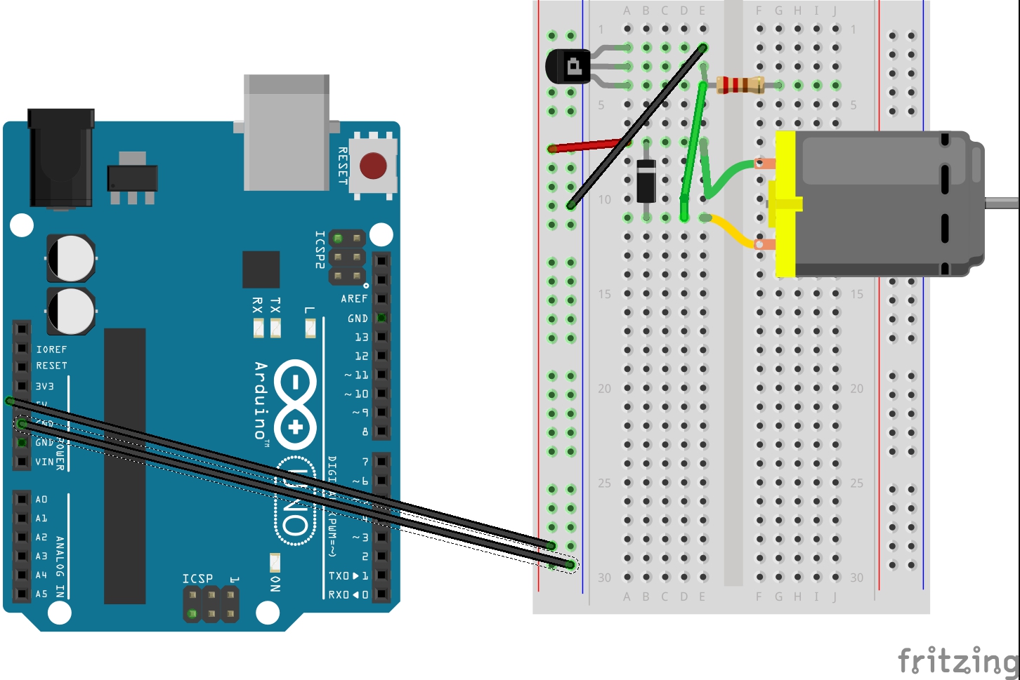
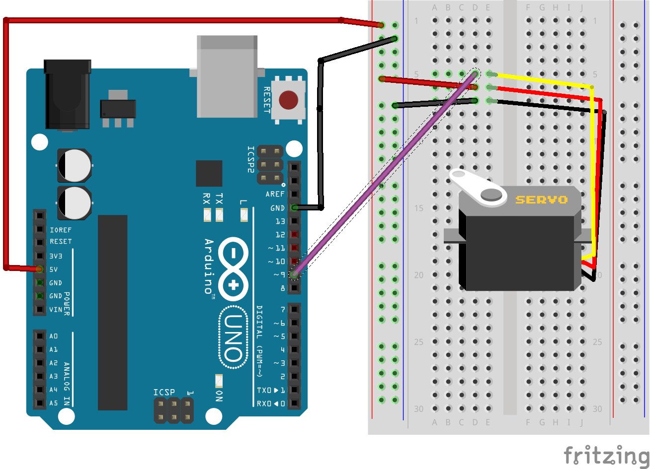
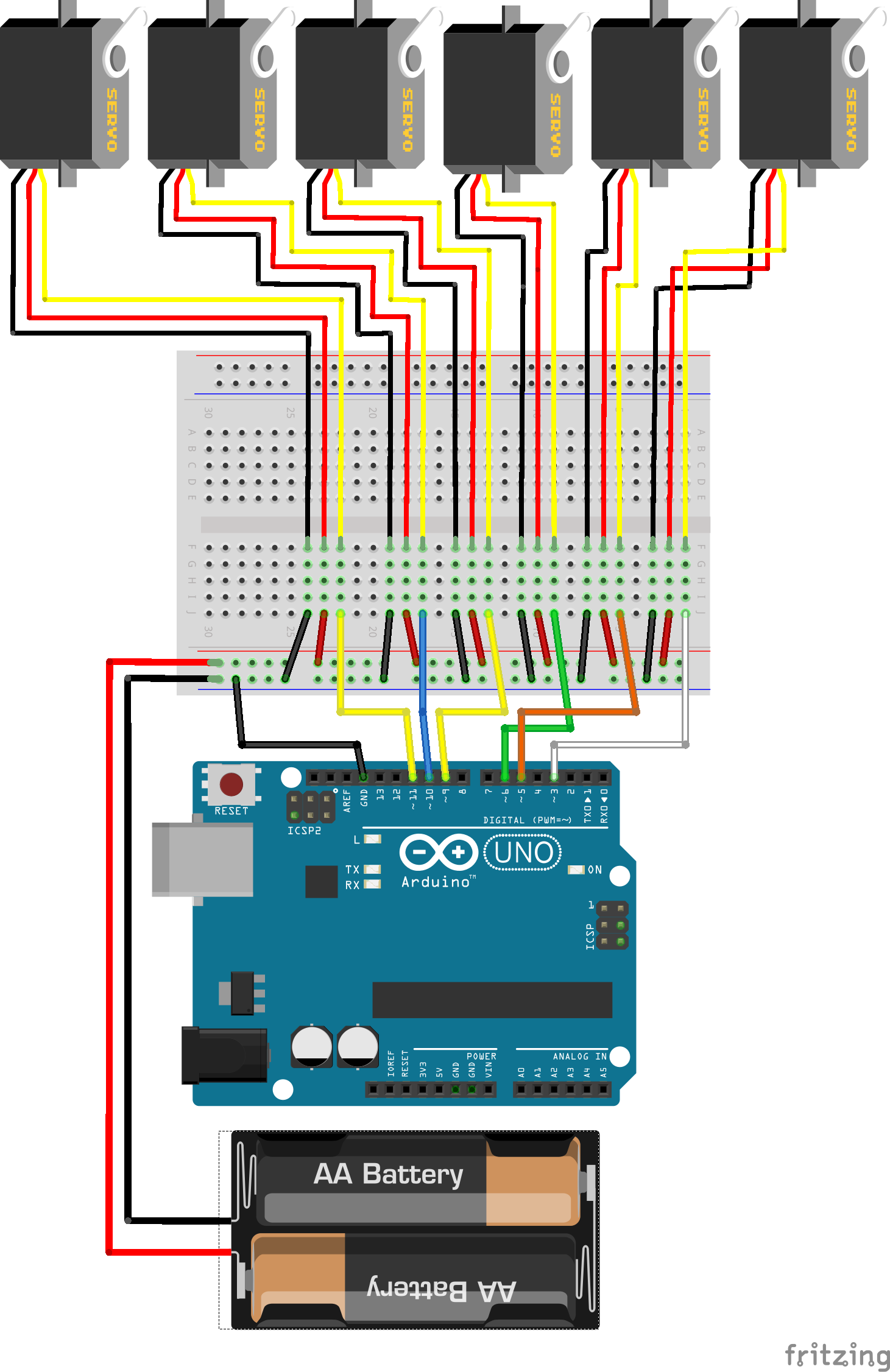
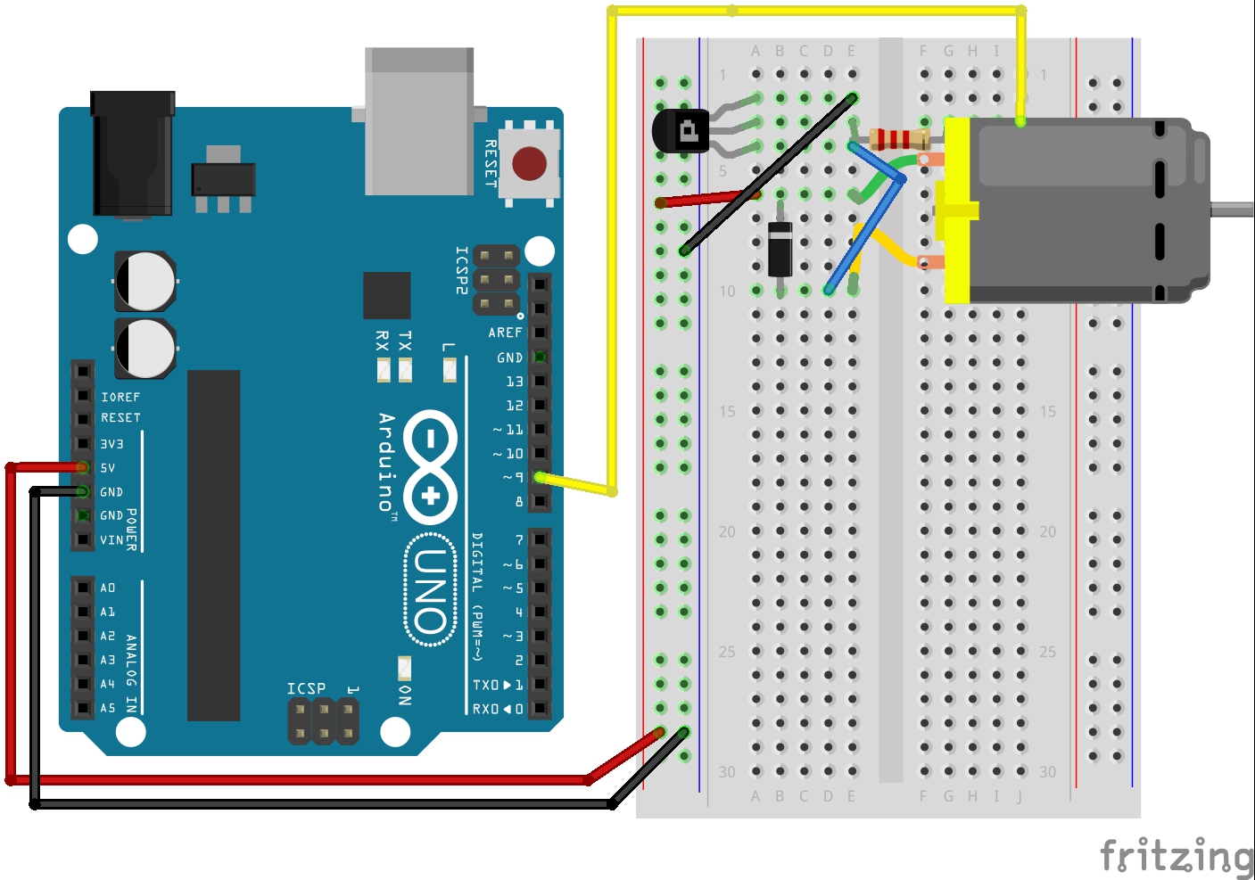
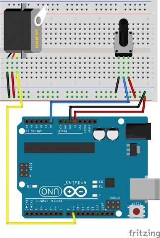
Fritzing diagram:

potentiomiddle finger

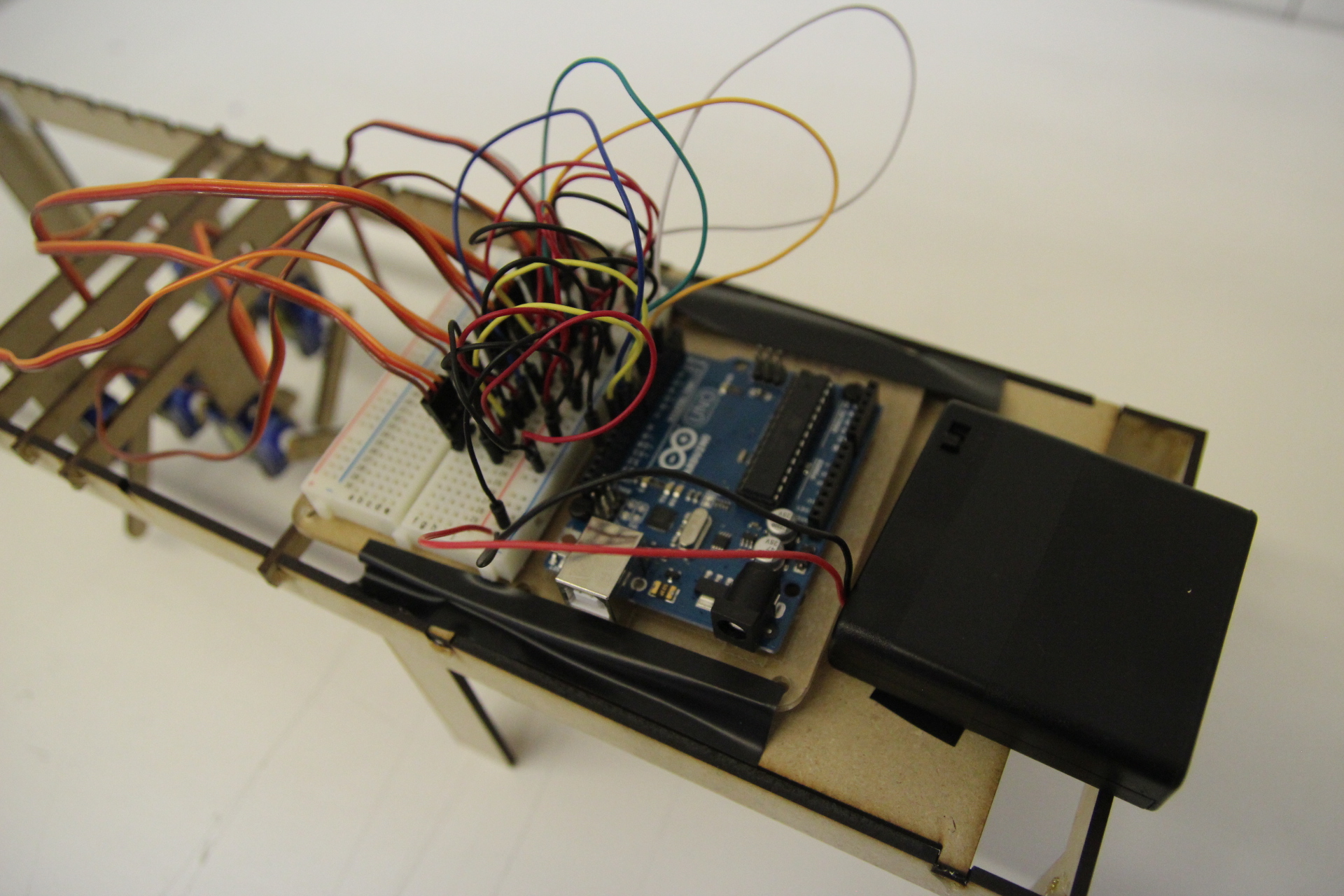
Arduino code (borrowed under extenuating circumstances):

// Controlling a servo position using a potentiometer (variable resistor) 
// by Michal Rinott <http://people.interaction-ivrea.it/m.rinott> 
//code adopted under emergency circumstances

#include  
 
Servo myservo;  // create servo object to control a servo 
 
int potpin = 0;  // analog pin used to connect the potentiometer
int val;    // variable to read the value from the analog pin 
 
void setup() 
{ 
  myservo.attach(9);  // attaches the servo on pin 9 to the servo object 
}  
 
void loop() 
{ 
  val = analogRead(potpin);            // reads the value of the potentiometer (value between 0 and 1023) 
  val = map(val, 0, 1023, 0, 179);     // scale it to use it with the servo (value between 0 and 180) 
  myservo.write(val);                  // sets the servo position according to the scaled value 
  delay(15);                           // waits for the servo to get there 
}

Monkey Monkey

For my automaton I made a swinging monkey using a cereal box, three plastic knives, real leaves and an arduino with servo. I used a simple sweep code for the servo and attached the monkey to the knife (for support) which is attached to the servo. Sadly, the monkey’s limbs are magnetic so the hand and feet kept sticking together. In general, though, this was a very fun project to work with and show people.

IMG_3823
Untitled Sketch_bb

#include  
 
Servo myservo;  // create servo object to control a servo 
                // twelve servo objects can be created on most boards
 
int pos = 0;    // variable to store the servo position 
 
void setup() 
{ 
  myservo.attach(9);  // attaches the servo on pin 9 to the servo object 
} 
 
void loop() 
{ 
  for(pos = 0; pos < = 120; pos += 1) // goes from 0 degrees to 180 degrees 
  {                                  // in steps of 1 degree 
    myservo.write(pos);              // tell servo to go to position in variable 'pos' 
    delay(15);                       // waits 15ms for the servo to reach the position 
  } 
  for(pos = 120; pos>=0; pos-=1)     // goes from 180 degrees to 0 degrees 
  {                                
    myservo.write(pos);              // tell servo to go to position in variable 'pos' 
    delay(15);                       // waits 15ms for the servo to reach the position 
  } 
} 

“Learning” Clair Chin

Here is my glorious wooden creation. The concept- I learned about what sex is in an a very basic way that I could understand, the penis goes into the vagina. I’m sure peoples’experiences in learning about sex differ greatly but sex is something fundamental to humans that we learn about at typically a young age. Sex is not so black and white or simple or anything like the explanation “the penis goes into the vagina”- thats something I wanted to comment on. Anyway, chaneling my childhood confusion on the subject of sex I made this odd object.

video documentation

sketches:
IMG_3232

fritzing diagram:
motorblocks_bb

code:

/*     -----------------------------------------------------------
 *     |  Arduino Experimentation Kit Example Code               |
 *     |  CIRC-03 .: Spin Motor Spin :. (Transistor and Motor)   |
 *     -----------------------------------------------------------
 * 
 * The Arduinos pins are great for driving LEDs however if you hook 
 * up something that requires more power you will quickly break them.
 * To control bigger items we need the help of a transistor. 
 * Here we will use a transistor to control a small toy motor
 * 
 * http://tinyurl.com/d4wht7
 *
 */

int motorPin = 9;  // define the pin the motor is connected to
                   // (if you use pin 9,10,11 or 3you can also control speed)

/*
 * setup() - this function runs once when you turn your Arduino on
 * We set the motors pin to be an output (turning the pin high (+5v) or low (ground) (-))
 * rather than an input (checking whether a pin is high or low)
 */
void setup()
{
 pinMode(motorPin, OUTPUT); 
}


/*
 * loop() - this function will start after setup finishes and then repeat
 * we call a function called motorOnThenOff()
 */

void loop()                     // run over and over again
{
 motorOnThenOff();
 //motorOnThenOffWithSpeed();
 //motorAcceleration();
}

/*
 * motorOnThenOff() - turns motor on then off 
 * (notice this code is identical to the code we used for
 * the blinking LED)
 */
void motorOnThenOff(){
  int onTime = 2500;  //the number of milliseconds for the motor to turn on for
  int offTime = 0; //the number of milliseconds for the motor to turn off for
  
  digitalWrite(motorPin, HIGH); // turns the motor On
  delay(onTime);                // waits for onTime milliseconds
 // digitalWrite(motorPin, LOW);  // turns the motor Off
  //delay(offTime);               // waits for offTime milliseconds
}

/*
 * motorOnThenOffWithSpeed() - turns motor on then off but uses speed values as well 
 * (notice this code is identical to the code we used for
 * the blinking LED)
 */
void motorOnThenOffWithSpeed(){
  
  int onSpeed = 255;  // a number between 0 (stopped) and 255 (full speed) 
  int onTime = 2500;  //the number of milliseconds for the motor to turn on for
  
  int offSpeed = 50;  // a number between 0 (stopped) and 255 (full speed) 
  int offTime = 0; //the number of milliseconds for the motor to turn off for
  
  analogWrite(motorPin, onSpeed);   // turns the motor On
 // delay(onTime);                    // waits for onTime milliseconds
//analogWrite(motorPin, offSpeed);  // turns the motor Off
  //delay(offTime);                   // waits for offTime milliseconds
}

/*
 * motorAcceleration() - accelerates the motor to full speed then
 * back down to zero
*/
void motorAcceleration(){
  int delayTime = 50; //milliu;seconds between each speed step
  
  //Accelerates the motor
  for(int i = 0; i &lt; 256; i++){ //goes through each speed from 0 to 255
    analogWrite(motorPin, i);   //sets the new speed
    delay(delayTime);           // waits for delayTime milliseconds
  }
  
  //Decelerates the motor
  for(int i = 255; i &gt;= 0; i--){ //goes through each speed from 255 to 0
    analogWrite(motorPin, i);   //sets the new speed
    delay(delayTime);           // waits for delayTime milliseconds
  }
}

Automaton: Physical Physics Simulation

photo(2)

The Physical Physics Simulation is a miniature mechanical self contained universe that consists of one body and three universal constants (gravity, friction, and elasticity).

The machine was inspried by events that live inside boxes, cabinets of curiosity, and the orrery, which is essentially a solar system simulation.

Screen Shot 2014-11-10 at 4.34.17 PM

// simple physics for physical physics simulation
// by luca and zach

#include 

Servo servoX;
Servo servoY;

// position
float px = 180;
float py = 0;

// velocity
float vx = 8;
float vy = 0;

float g = 800 * 0.001f; // gravitational constant
float f = 0.9f;         // friction constant
float e = 0.98f;        // elasticity constant

float tickTime = 105; // how often to update? 

void setup()
{
  servoX.attach(10);
  servoY.attach(11);
}

void loop()
{
  // add gravity to y veloctity (ball falling)
  vy += g;
  
  // update position
  px += vx;
  py += vy;
  
  // save old positions
  float ppx = px;
  float ppy = py;
  
  // collision with walls
  if(px < 0 || px > 180) {
    px = ppx;
    vx = -vx*e;
  }
  if(py < 0 || py > 180) {
    py = ppy;
    vy = -vy*e;
  }
  
  // friction (ball on floor)
  if(py < 2) {
    vx = vx * f;
  }
  
  // bounds
  float agpx;
  float agpy;
  agpx = map(px, 0, 180, 35, 150);
  agpy = map(py, 0, 180, 25, 165);
  
  //move servos
  servoX.write(agpx);
  delay(tickTime);
  servoY.write(agpy);
  delay(tickTime);
  
}

Separation Engine

IMG_8143

The Separation Engine is a machine that types pre-determined messages onto a keyboard, indirectly interfacing with a computer to write these messages for the viewer.

I originally intended for this machine to be able to type any character on the top row of a qwerty keyboard. However, the Arduino Mega I needed to make this happen never shipped, so I was ham-stringed to 6 servos, 2 of which were needed for the space bar and the enter key.

Since this piece is so much about communication, I decided to limit myself to the words ‘i’ and ‘you’, using these as a basis for morse code. Currently, the piece types the following, looping forever:

Screen Shot 2014-11-10 at 12.49.59

this translates to ‘I don’t want this.’ I recently ended a relationship, and this ended up guiding the subject matter of the piece.

IMG_8144

IMG_8145

I’m ultimately dissatisfied with the piece, since I wanted it to originally be so much more than what it currently is. There’s also a lot more I would like to do with this technology. There are a lot of different designs I’ve been considering for ways to hit the keys that would be more engaging and faster than this setup. I also want to change the subject matter. something that I discovered while making this (with the help of Luca) was that it would be entirely feasible to make a machine that could re-write the code that programs it, and then upload that code to the machine itself.

Tyro_bb

#include <Servo.h> 
 
Servo ent;  // create servo object to control a servo 
Servo o;                // twelve servo objects can be created on most boards
Servo i;
Servo u;
Servo spc;
Servo y;
 
int d = 100;
 
void setup() 
{ 
  ent.attach(3);  // attaches the servo on pin 9 to the servo object 
  o.attach(5);
  i.attach(6);
  u.attach(9);
  spc.attach(10);
  y.attach(11);
} 


void hitent(){
  ent.write(30);
    delay(d);
  ent.write(45);
    delay(d);
}

void hito(){
  o.write(25); 
    delay(d);
  o.write(40); 
    delay(d);
}

void hiti(){
  i.write(152);
    delay(d); 
  i.write(135); 
    delay(d);
}

void hitu(){
  u.write(15); 
    delay(d);
  u.write(30); 
    delay(d);
}

void hitspc(){
    spc.write(140);
    delay(d); 
  spc.write(130); 
    delay(d);
}

void hity(){
    y.write(145); 
    delay(d);
  y.write(130); 
    delay(d);
}


void hityou(){
  hity();
  hito();
  hitu();
  hitspc();
}  

void hitI(){
 hiti();
 hitspc(); 
}

 
void loop() 
{ 
  hitI();  //i
  hitI();
  hitent();
  hitent();
  
  hityou();//dont
  hitI();
  hitI();
  hitent();
  hityou();
  hityou();
  hityou();
  hitent();
  hityou();
  hitI();
  hityou();
  hitent();
  hityou();
  hitent();
  hitent();
  
  hitI();  //want
  hityou(); 
  hityou(); 
  hitent();
  hitI(); 
  hityou(); 
  hitent();
  hityou();
  hitI(); 
  hitent();
  hityou(); 
  hitent();
  hitent();

  hityou();//this
  hitent();
  hitI(); 
  hitI(); 
  hitI(); 
  hitI(); 
  hitent();
  hitI(); 
  hitI(); 
  hitent();
  hitI(); 
  hitI(); 
  hitI(); 
  hitent();
  hitent();
  hitent();
}


At the Dentist

So what I was trying to do was make a scene at the dentist where the dentist would try to pull out the tooth of the patient and the patient would scream with his legs being raised and his head going up. So I searched for some time to see how other automatons functioned. I sketched out the automaton parts.

20141110_153418

20141110_153443


I used the laser cutter to cut out the parts on a 1/8 thick paper but it was too thin that it wouldn’t work. So I stacked 3 papers on top of each other so it would work better. Three out of two had worked and the last one, where the horizontal movement was transferred to the vertical movements were not functioning properly due to the less amount of friction that the paper had. I tried to fix it but the paper wasn’t strong enough to hold it tightly in place. Below is the video to the automaton that I had made.

For the Arduino part I just used the sample code given instead of trying something difficult since I had too much trouble with the making the gears part that I really didn’t have much time to invest in coding.

CIRC03


int motorPin = 9;  // define the pin the motor is connected to
                   // (if you use pin 9,10,11 or 3you can also control speed)

/*
 * setup() - this function runs once when you turn your Arduino on
 * We set the motors pin to be an output (turning the pin high (+5v) or low (ground) (-))
 * rather than an input (checking whether a pin is high or low)
 */
void setup()
{
 pinMode(motorPin, OUTPUT); 
}


/*
 * loop() - this function will start after setup finishes and then repeat
 * we call a function called motorOnThenOff()
 */

void loop()                     // run over and over again
{
 motorOnThenOff();
 //motorOnThenOffWithSpeed();
// motorOnThenOff(); 
motorOnThenOffWithSpeed(); 
//motorAcceleration(); 
 //motorAcceleration();
}

/*
 * motorOnThenOff() - turns motor on then off 
 * (notice this code is identical to the code we used for
 * the blinking LED)
 */
void motorOnThenOff(){
  int onTime = 2500;  //the number of milliseconds for the motor to turn on for
  int offTime = 1000; //the number of milliseconds for the motor to turn off for
  
  digitalWrite(motorPin, HIGH); // turns the motor On
  delay(onTime);                // waits for onTime milliseconds
  digitalWrite(motorPin, LOW);  // turns the motor Off
  delay(offTime);               // waits for offTime milliseconds
}

/*
 * motorOnThenOffWithSpeed() - turns motor on then off but uses speed values as well 
 * (notice this code is identical to the code we used for
 * the blinking LED)
 */
void motorOnThenOffWithSpeed(){
  
  int onSpeed = 200;  // a number between 0 (stopped) and 255 (full speed) 
  int onTime = 2500;  //the number of milliseconds for the motor to turn on for
  
  int offSpeed = 50;  // a number between 0 (stopped) and 255 (full speed) 
  int offTime = 1000; //the number of milliseconds for the motor to turn off for
  
  analogWrite(motorPin, onSpeed);   // turns the motor On
  delay(onTime);                    // waits for onTime milliseconds
  analogWrite(motorPin, offSpeed);  // turns the motor Off
  delay(offTime);                   // waits for offTime milliseconds
}

/*
 * motorAcceleration() - accelerates the motor to full speed then
 * back down to zero
*/
void motorAcceleration(){
  int delayTime = 50; //milliseconds between each speed step
  
  //Accelerates the motor
  for(int i = 0; i < 256; i++){ //goes through each speed from 0 to 255     analogWrite(motorPin, i);   //sets the new speed     delay(delayTime);           // waits for delayTime milliseconds   }      //Decelerates the motor   for(int i = 255; i >= 0; i--){ //goes through each speed from 255 to 0
    analogWrite(motorPin, i);   //sets the new speed
    delay(delayTime);           // waits for delayTime milliseconds
  }
}

I think I should have tried different materials and maybe made it in bigger and thicker in size due to the fraction it had. And a little bet of miss placement and measuring caused a lot of trouble in this automaton, and that accuracy is really important in it. Also I think that the simple gears functioned well and that more time should be put into how the gears connect to each other rather than how motor can actually make it work.

Wind-Up Automaton Rocking Chair Boat!

From inception…

20141110_160050

to realization…

20141110_111901

20141110_111911

20141110_111918

20141110_111925

The wind-up automaton rocking chair was thoroughly outside of my comfort zone. I have lots of trouble executing precision cuts, which effective kinetic machinery requires. However, the laser cutter and calipers proved perfect tools for the job. I experimented with several different methods of connecting pieces which are evident throughout the piece, although most of the components are connected using Elmer’s glue. If I were to continue with this concept, I would scale the piece up to the point that someone could actually sit on it, and use a more powerful wind up motor. I would also gear down the motor, so as to create a less rapid rocking motion.