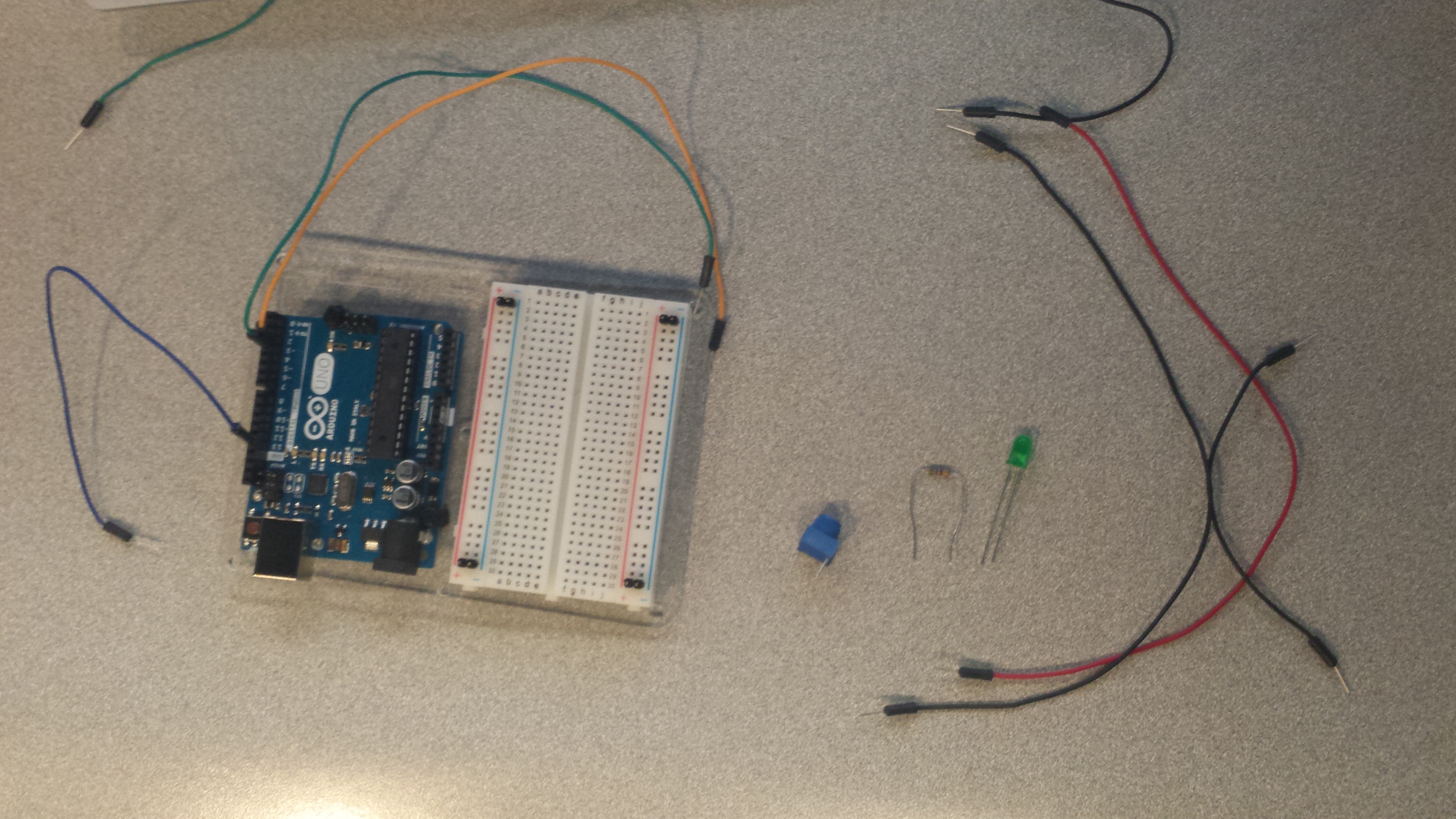
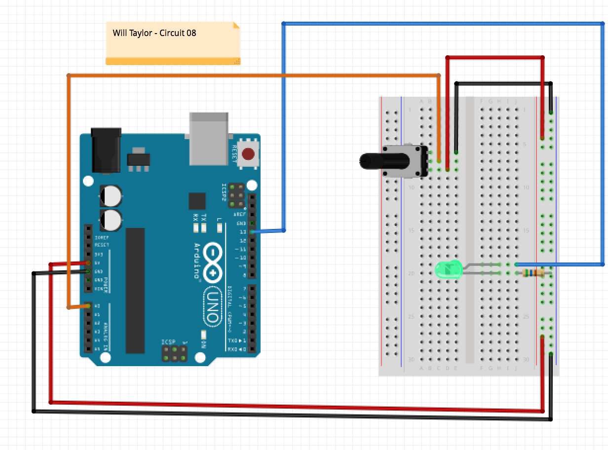
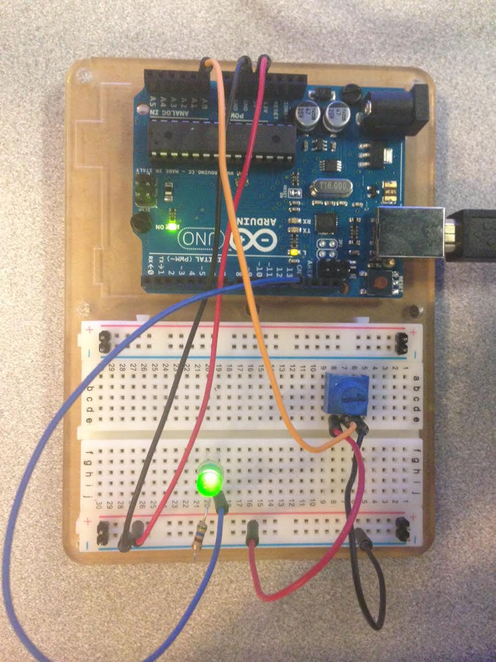
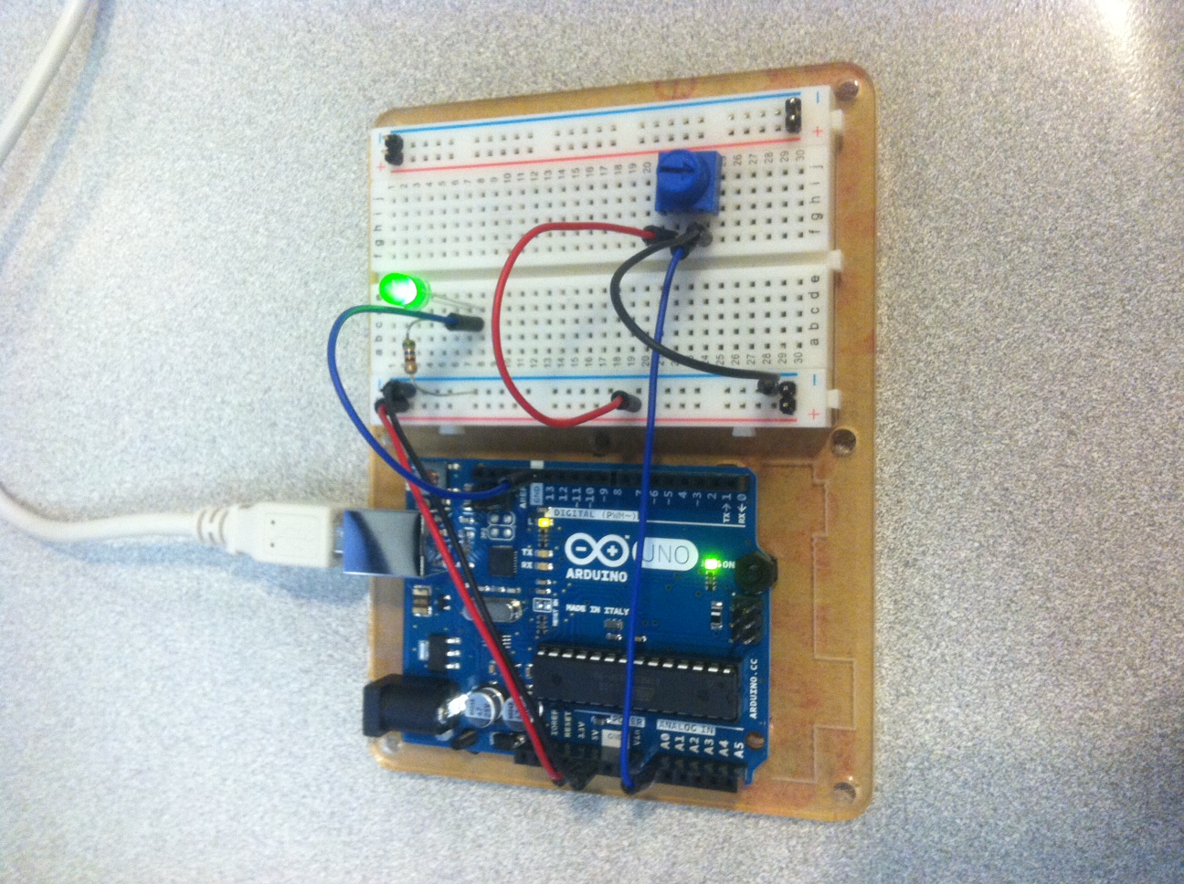
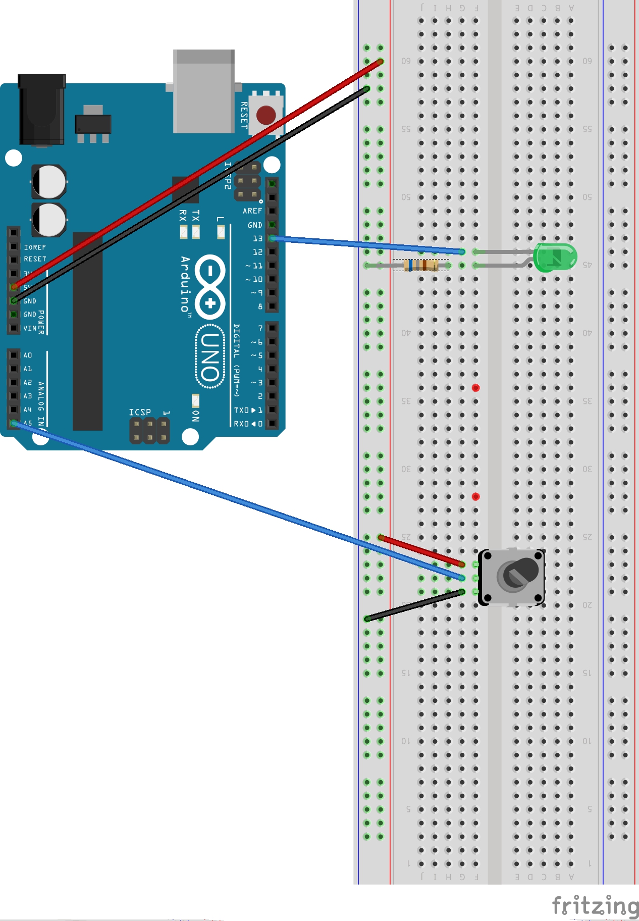
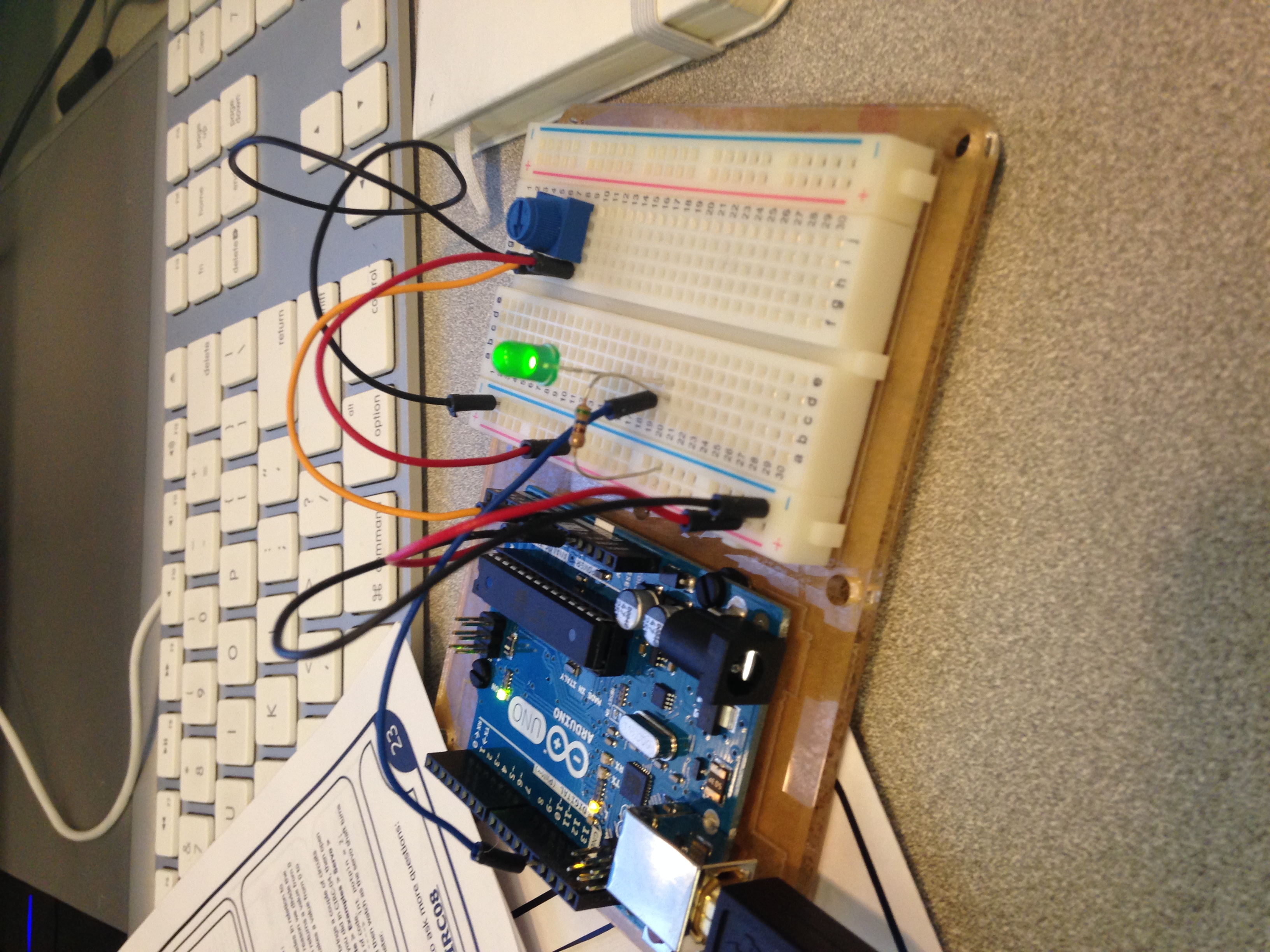
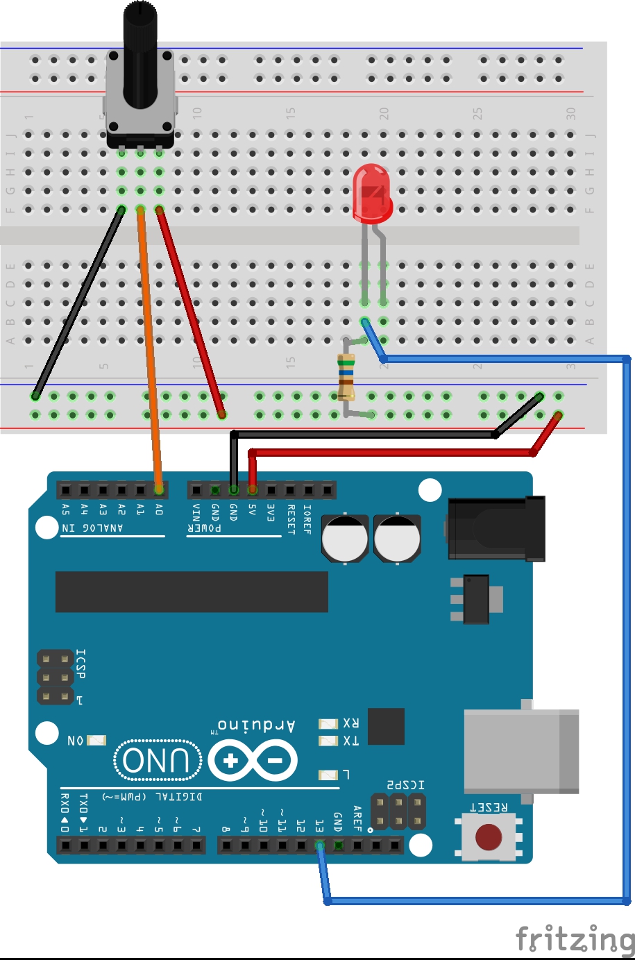
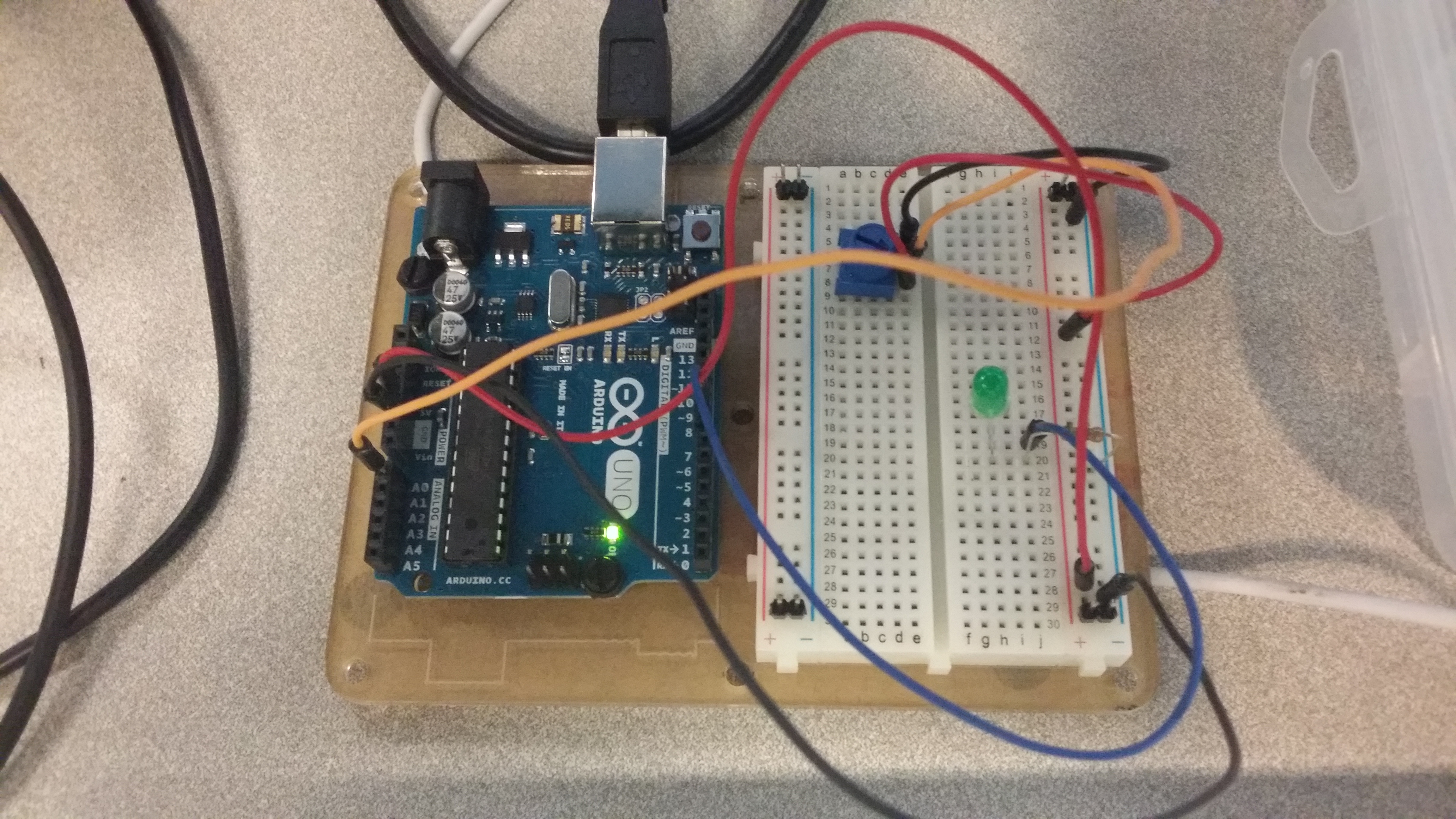
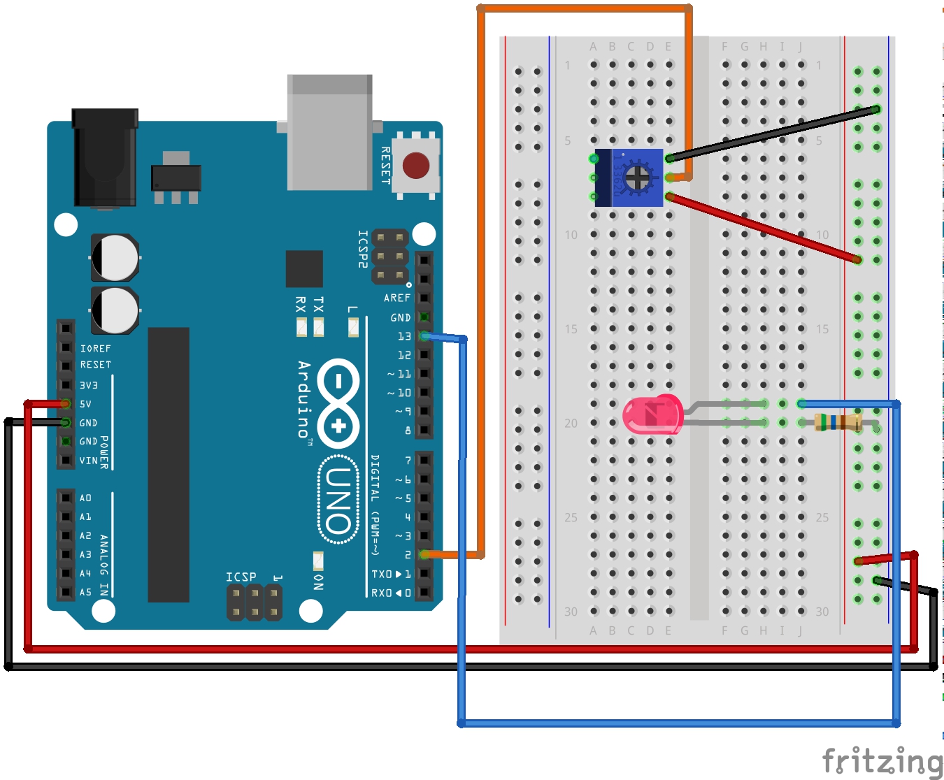
Variable Resistors
Code For potentiometer
/*
Analog Input
Demonstrates analog input by reading an analog sensor on analog pin 0 and
turning on and off a light emitting diode(LED) connected to digital pin 13.
The amount of time the LED will be on and off depends on
the value obtained by analogRead().
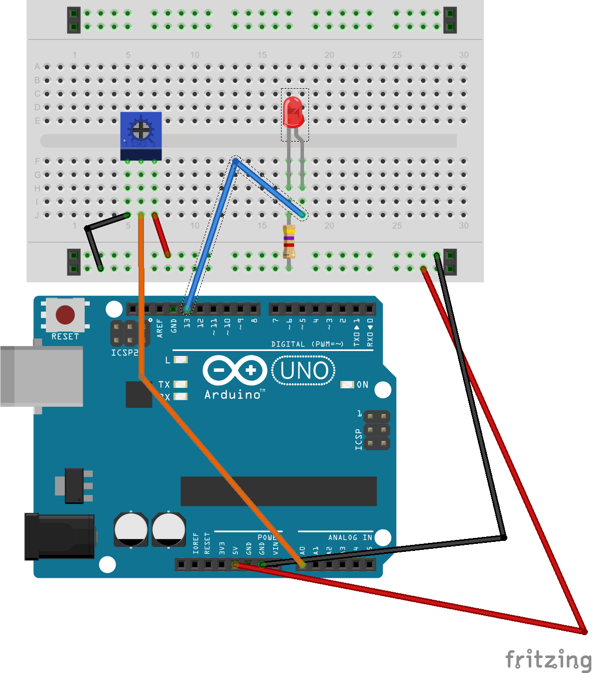
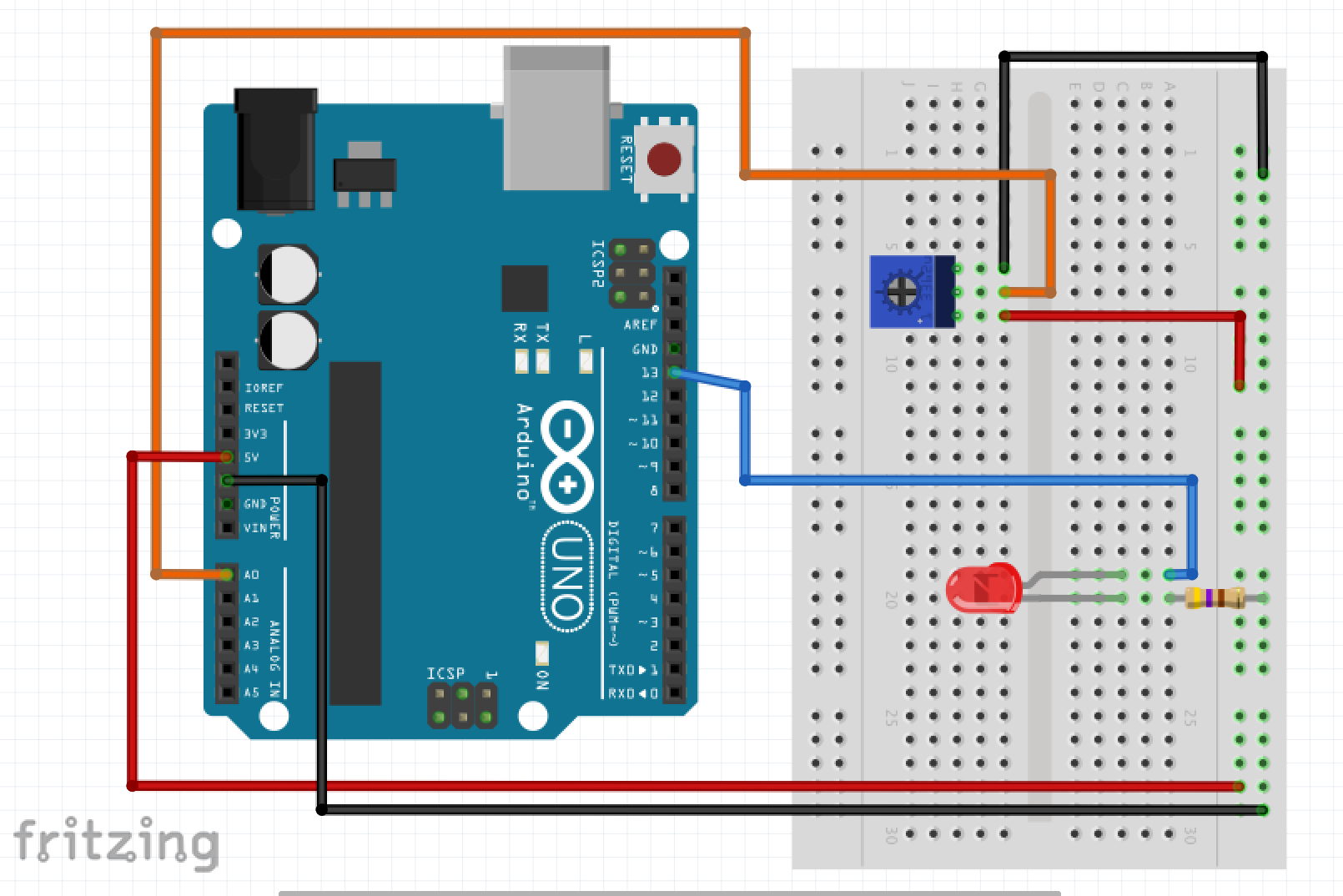
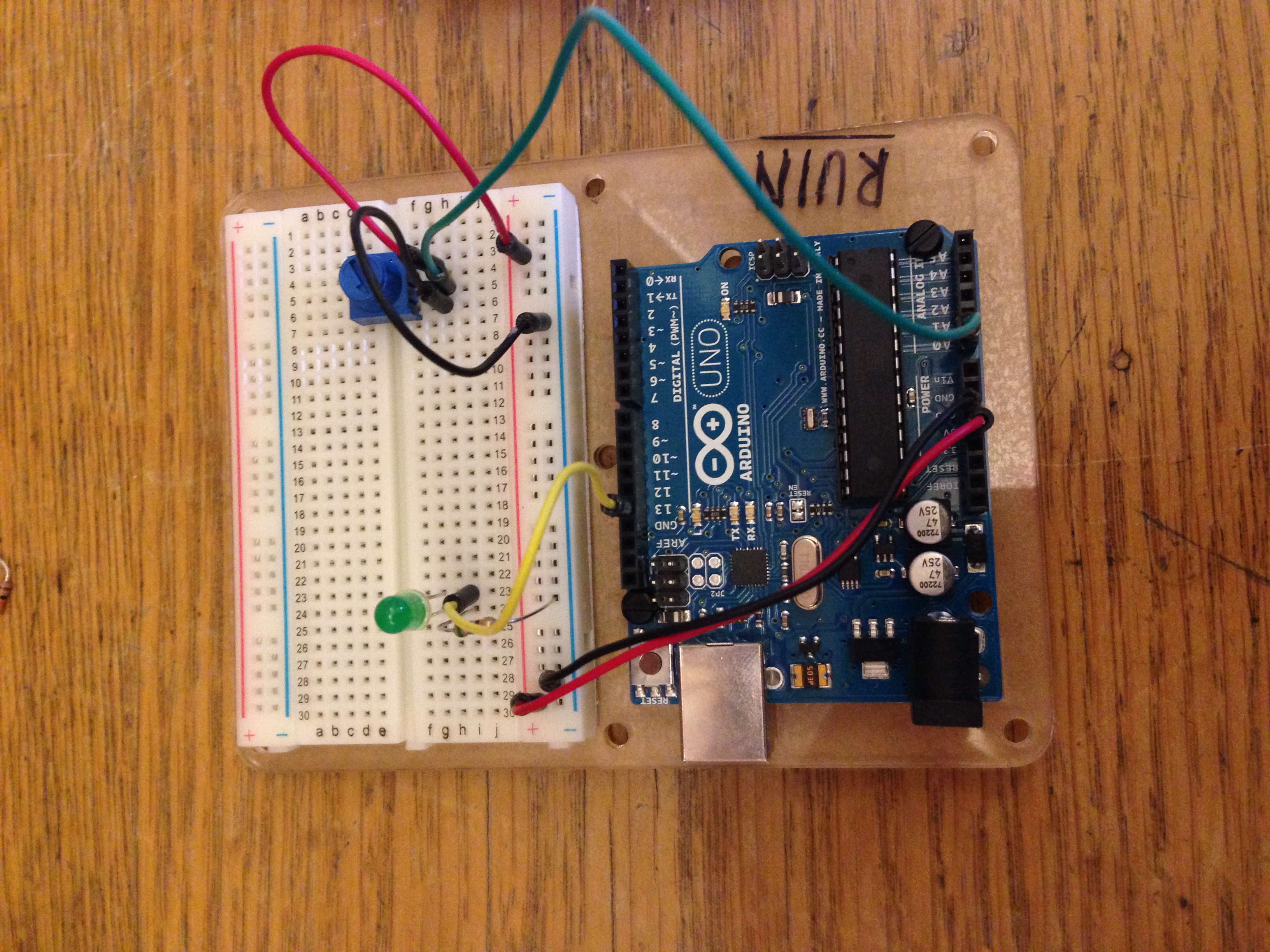
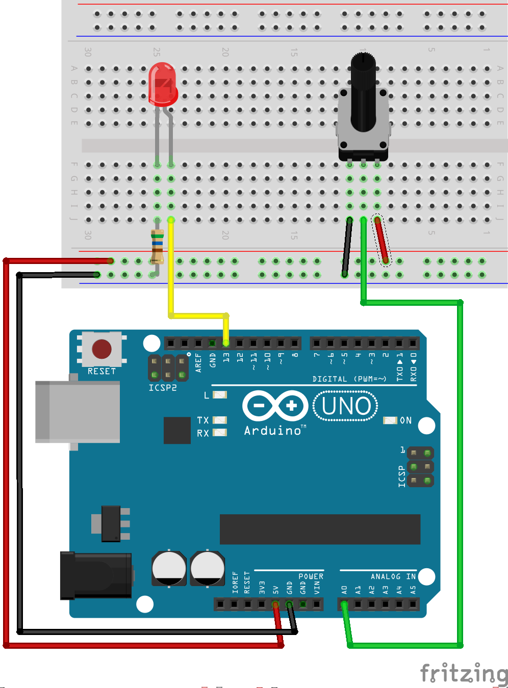
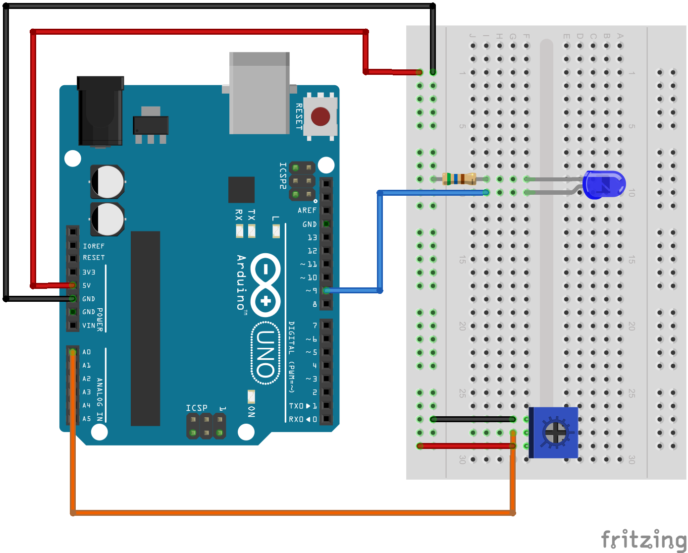
The circuit:
* Potentiometer attached to analog input 0
* center pin of the potentiometer to the analog pin
* one side pin (either one) to ground
* the other side pin to +5V
* LED anode (long leg) attached to digital output 13
* LED cathode (short leg) attached to ground
* Note: because most Arduinos have a built-in LED attached
to pin 13 on the board, the LED is optional.
 Created by David Cuartielles
 Modified 16 Jun 2009
 By Tom Igoe

 http://arduino.cc/en/Tutorial/AnalogInput

 */

int sensorPin = 0;    // select the input pin for the potentiometer
int ledPin = 13;      // select the pin for the LED
int sensorValue = 0;  // variable to store the value coming from the sensor

void setup() {
  // declare the ledPin as an OUTPUT:
  pinMode(ledPin, OUTPUT);
}

void loop() {
  // read the value from the sensor:
  sensorValue = analogRead(sensorPin);
  // turn the ledPin on
  digitalWrite(ledPin, HIGH);
  // stop the program for  milliseconds:
  delay(sensorValue);
  // turn the ledPin off:
  digitalWrite(ledPin, LOW);
  // stop the program for for  milliseconds:
  delay(sensorValue);
}
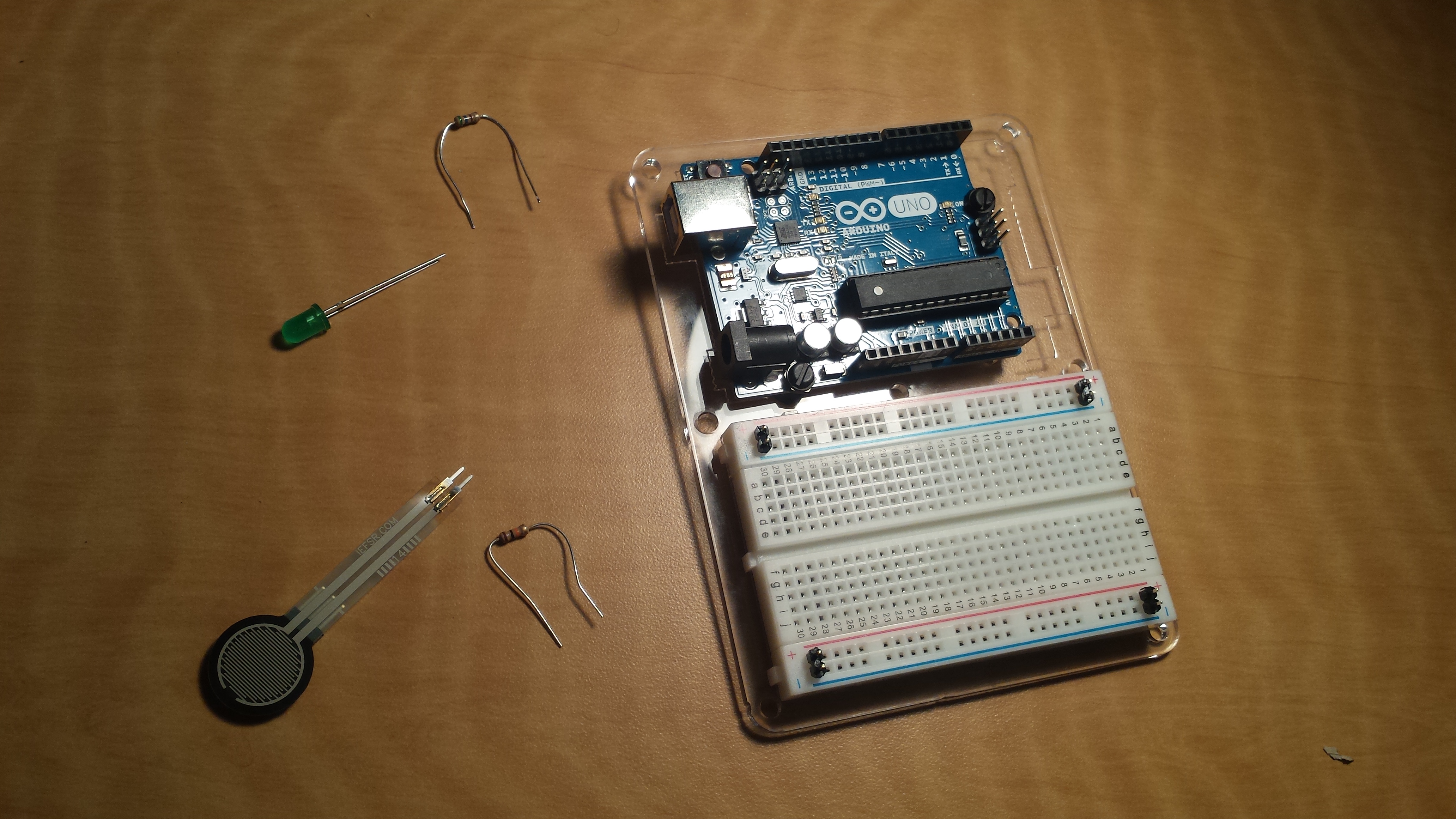
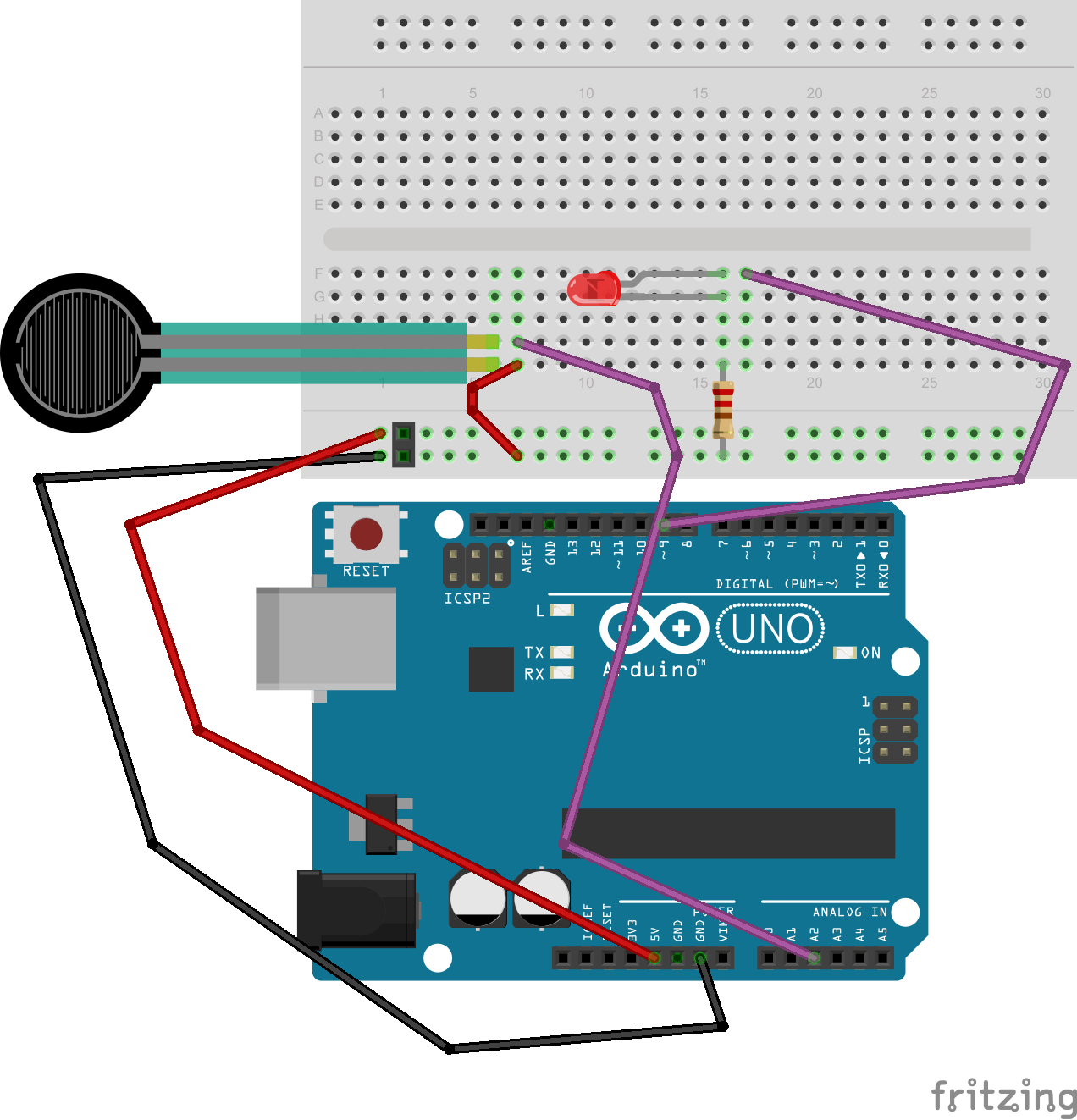
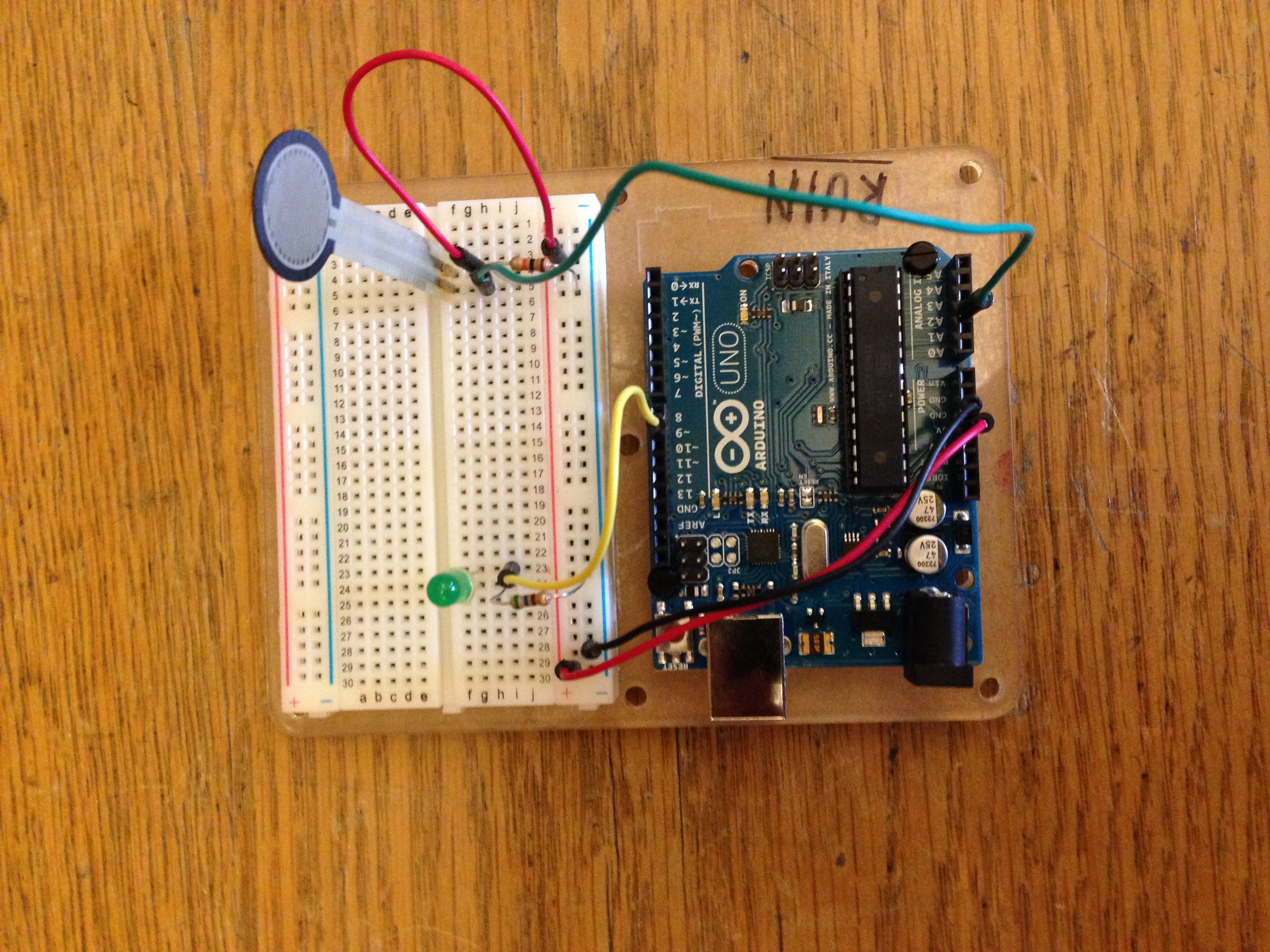
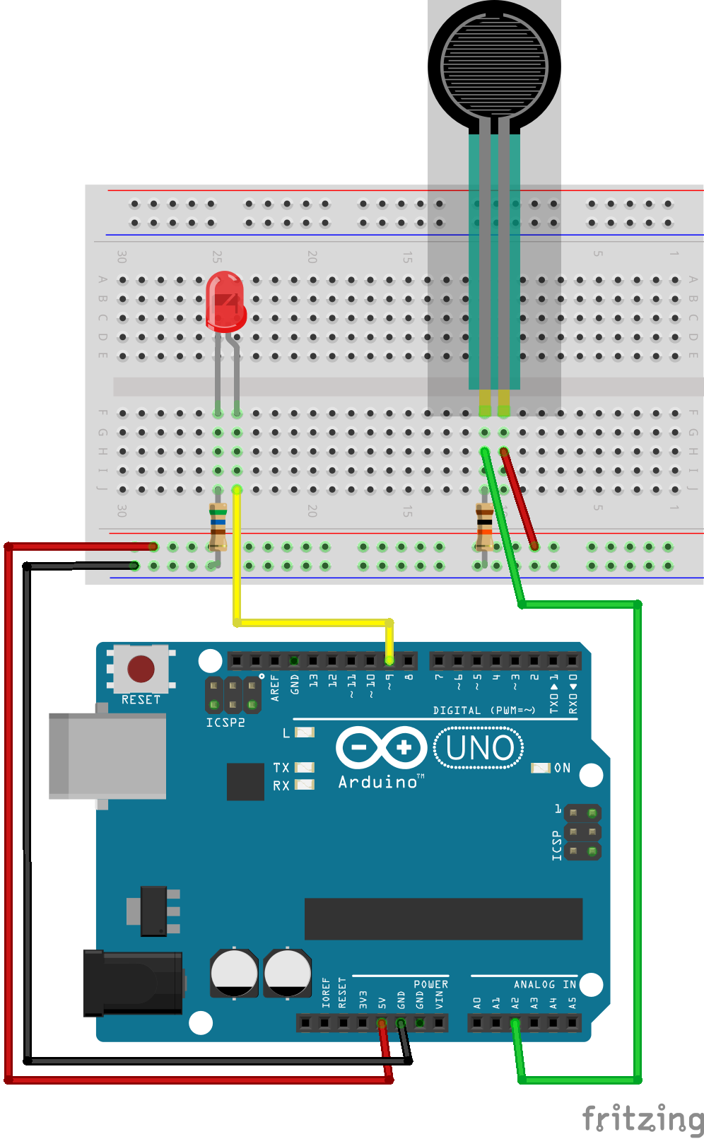
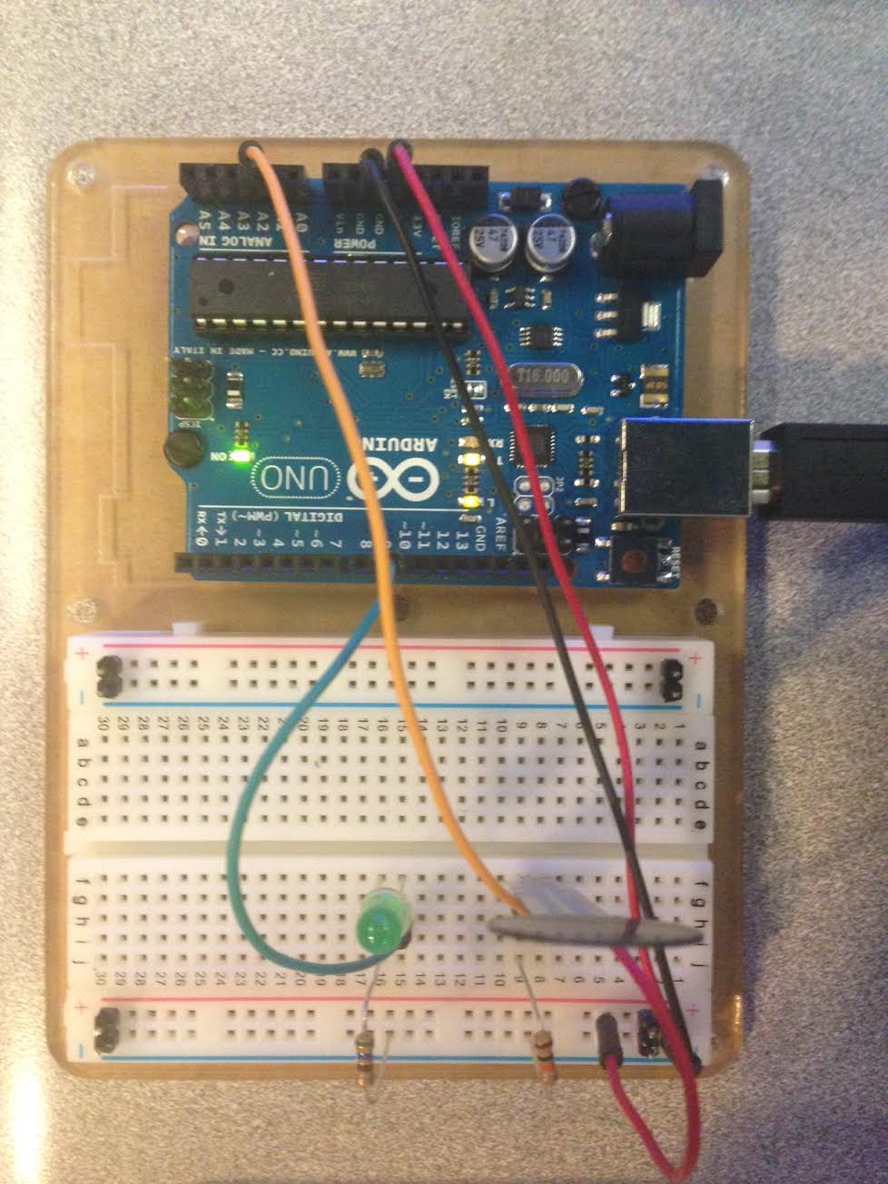
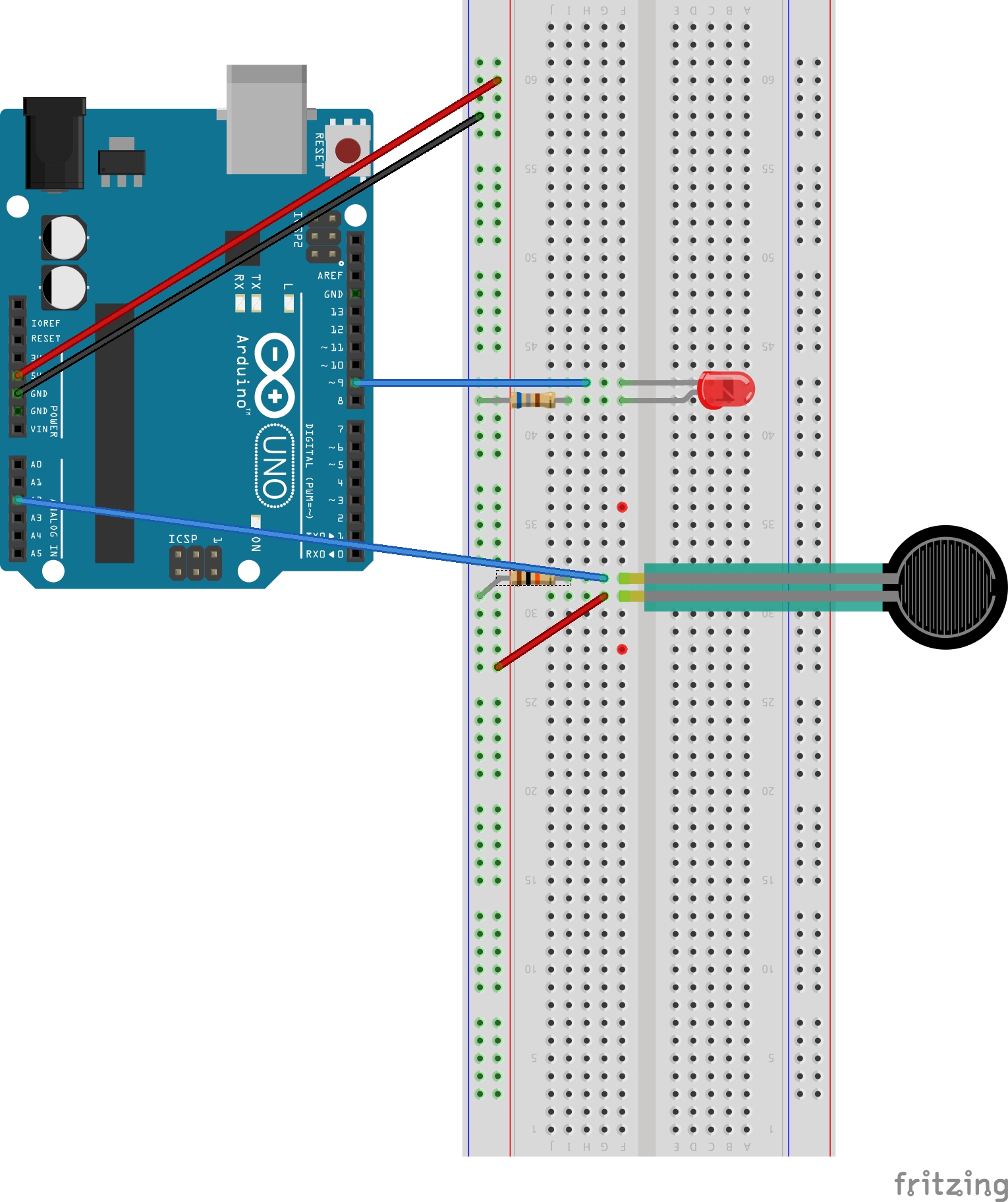
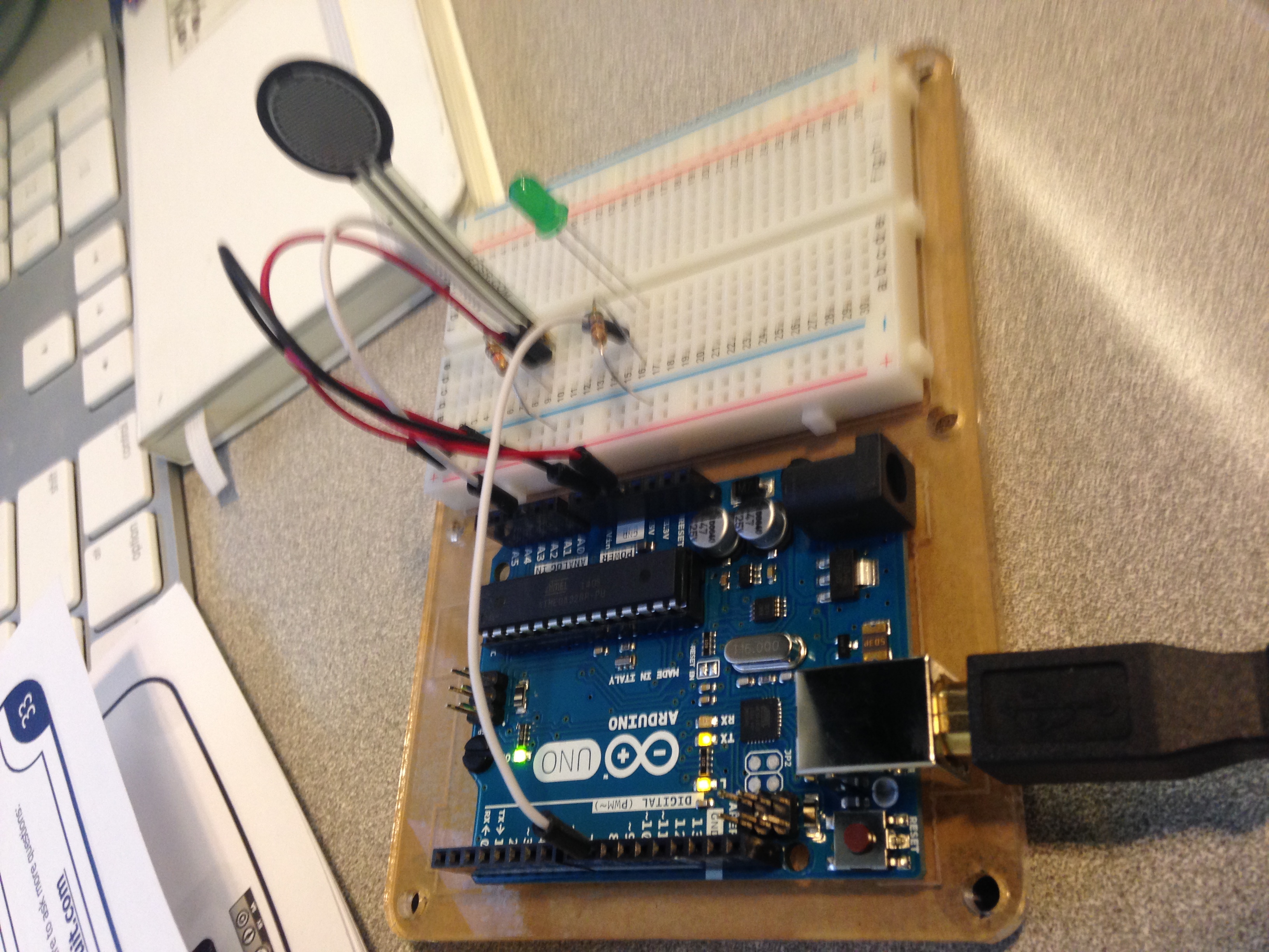
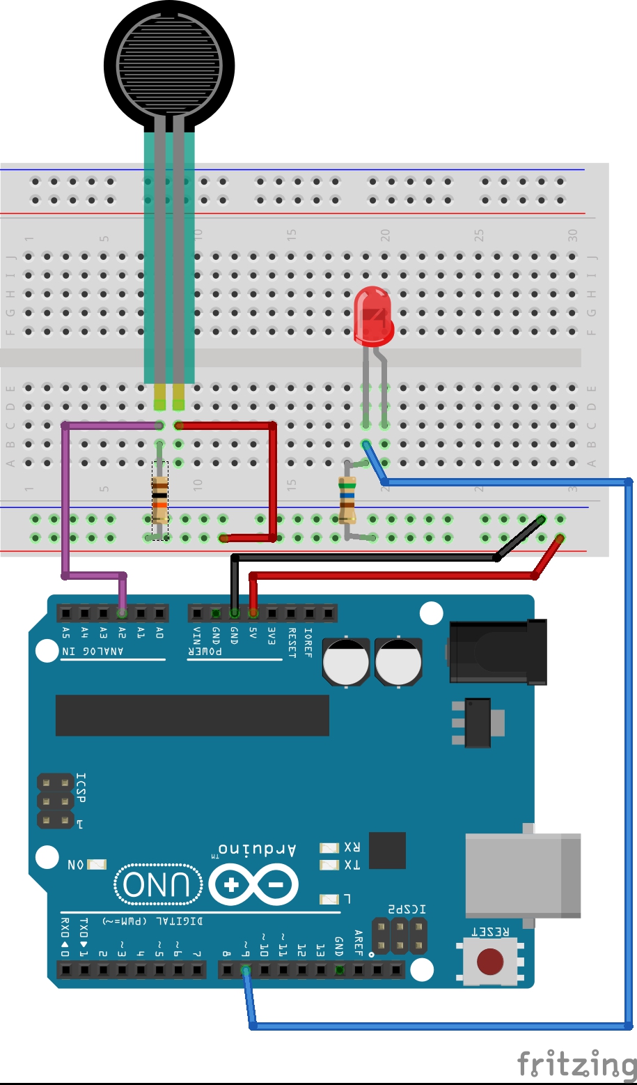
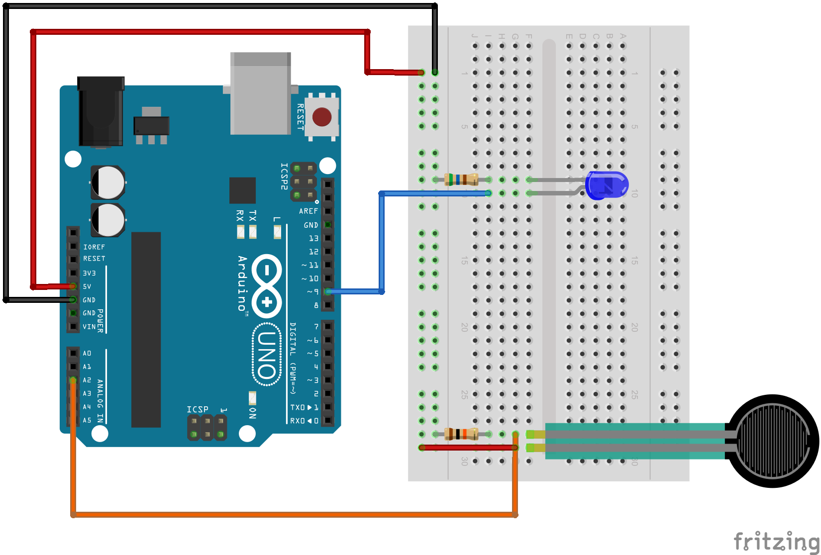
Code for force sensitive resistor
/*
 * Force Sensitive Resistor Test Code
 *
 * The intensity of the LED will vary with the amount of pressure on the sensor
 */

int sensePin = 2;    // the pin the FSR is attached to
int ledPin = 9;      // the pin the LED is attached to (use one capable of PWM)

void setup() {
  Serial.begin(9600);
  pinMode(ledPin, OUTPUT);  // declare the ledPin as an OUTPUT
}

void loop() {
  int value = analogRead(sensePin) / 4; //the voltage on the pin divded by 4 (to scale from 10 bits (0-1024) to 8 (0-255)
  analogWrite(ledPin, value);        //sets the LEDs intensity proportional to the pressure on the sensor
  Serial.println(value);              //print the value to the debug window
}