/*
  Button

 Turns on and off a light emitting diode(LED) connected to digital
 pin 13, when pressing a pushbutton attached to pin 7.


 The circuit:
 * LED attached from pin 13 to ground
 * pushbutton attached to pin 2 from +5V
 * 10K resistor attached to pin 2 from ground

 * Note: on most Arduinos there is already an LED on the board
 attached to pin 13.


 created 2005
 by DojoDave
 modified 17 Jun 2009
 by Tom Igoe

  http://www.arduino.cc/en/Tutorial/Button
 */

// constants won't change. They're used here to
// set pin numbers:
const int buttonPin = 2;     // the number of the pushbutton pin
const int ledPin =  13;      // the number of the LED pin

// variables will change:
int buttonState = 0;         // variable for reading the pushbutton status

void setup() {
  // initialize the LED pin as an output:
  pinMode(ledPin, OUTPUT);
  // initialize the pushbutton pin as an input:
  pinMode(buttonPin, INPUT);
}

void loop(){
  // read the state of the pushbutton value:
  buttonState = digitalRead(buttonPin);

  // check if the pushbutton is pressed.
  // if it is, the buttonState is HIGH:
  if (buttonState == HIGH) {
    // turn LED on:
    digitalWrite(ledPin, HIGH);
  }
  else {
    // turn LED off:
    digitalWrite(ledPin, LOW);
  }
}
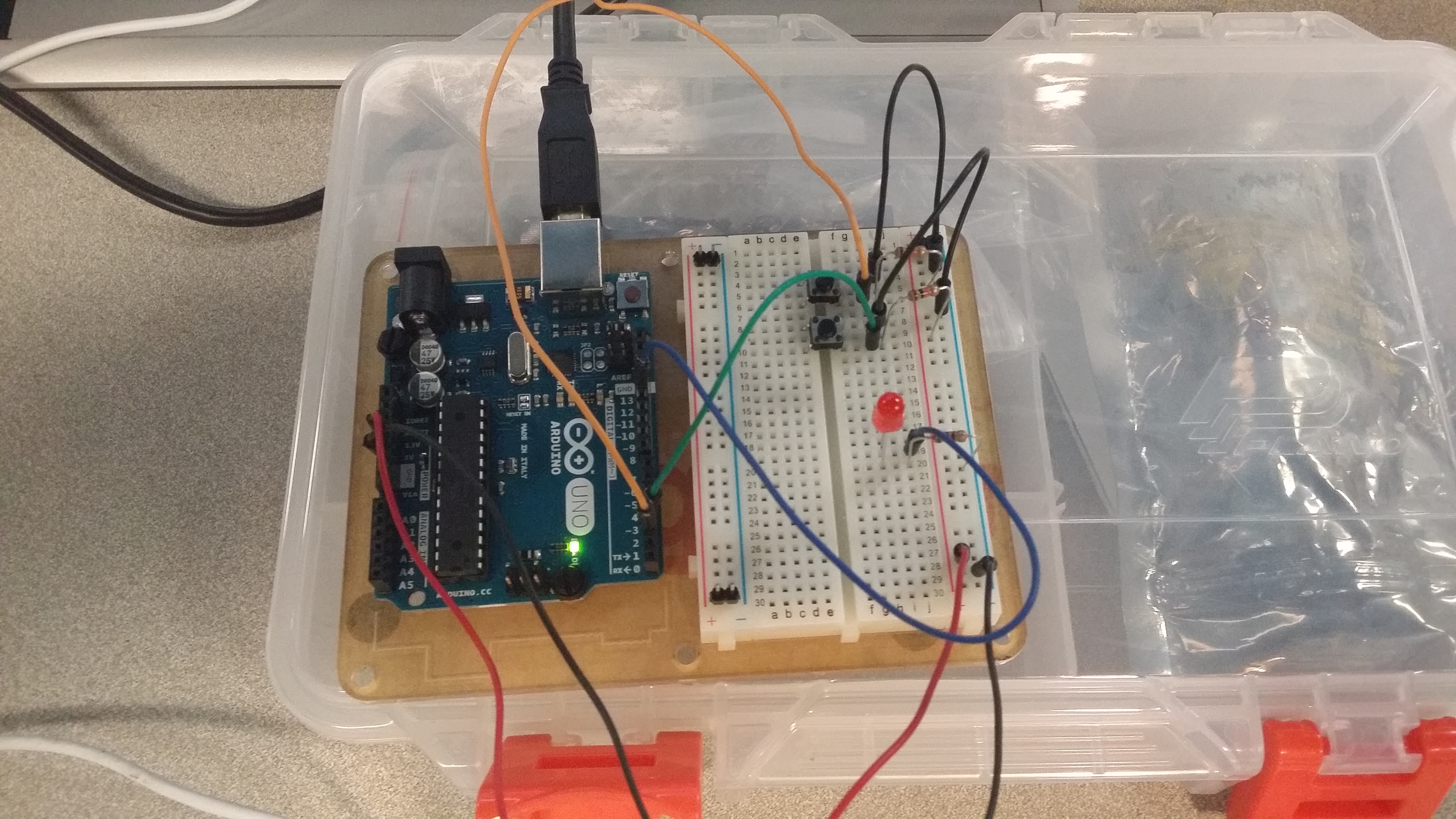
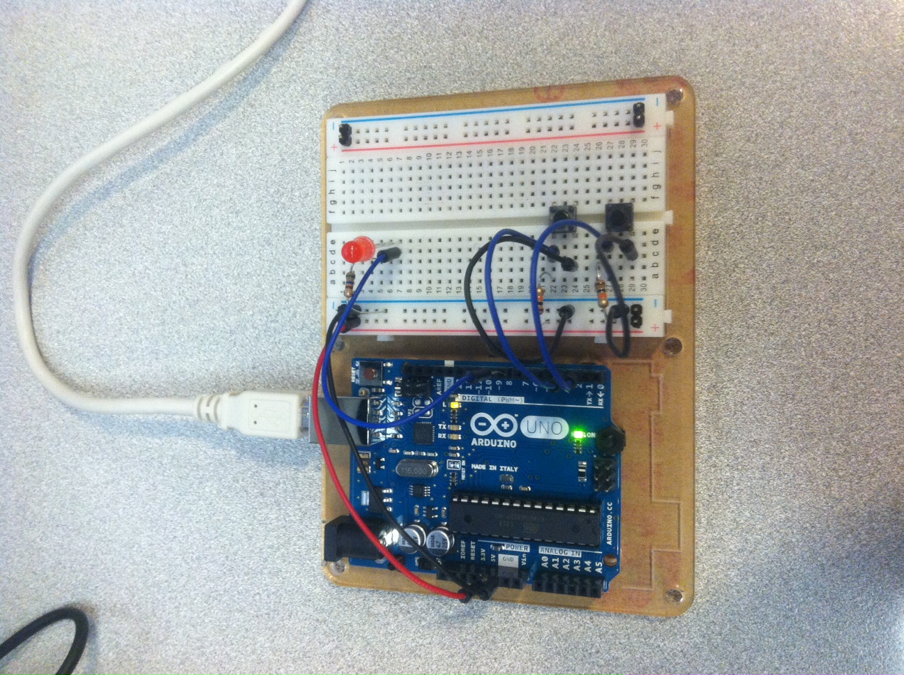
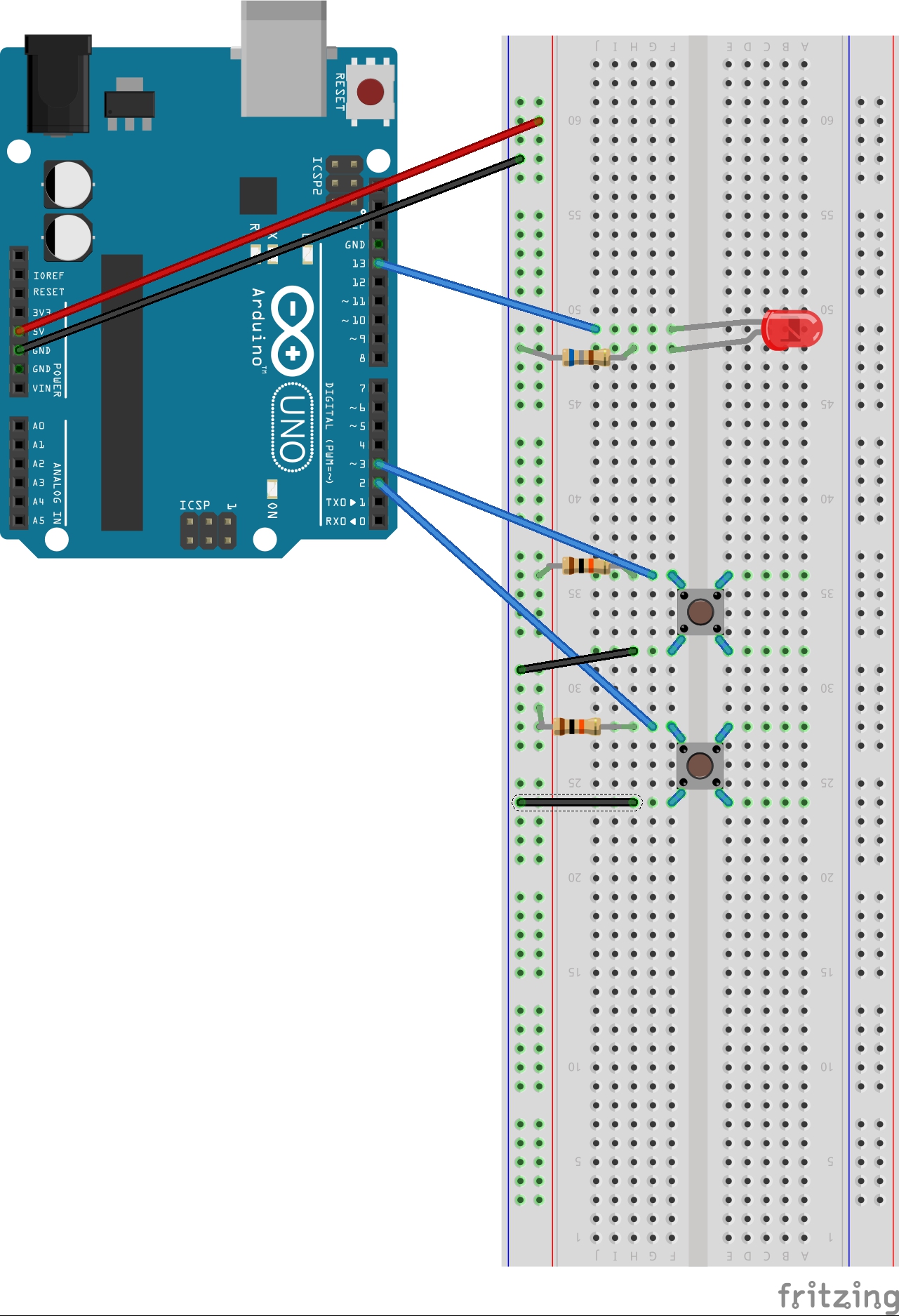
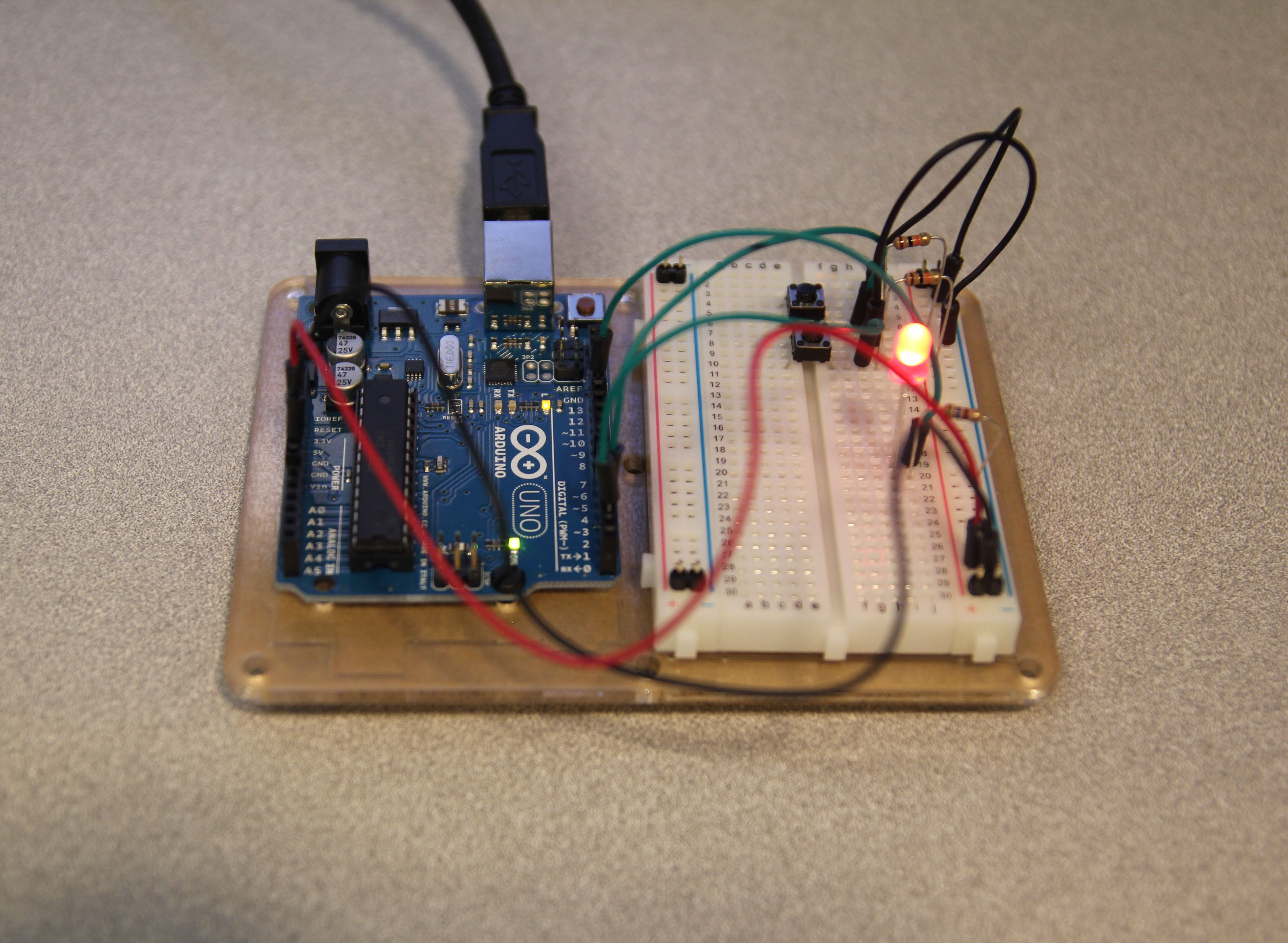
This is the first part of the LED working with one button:
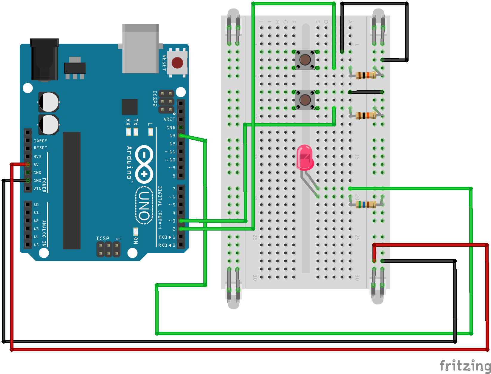
This is the second part (under “make it better”) of the LED controlled by two buttons:
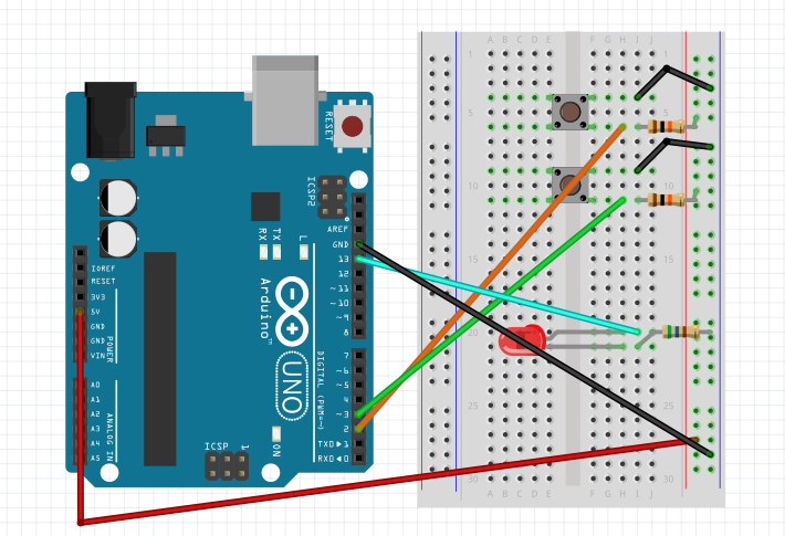
Third part (also under “make it better”) of the LED being faded by the two buttons:
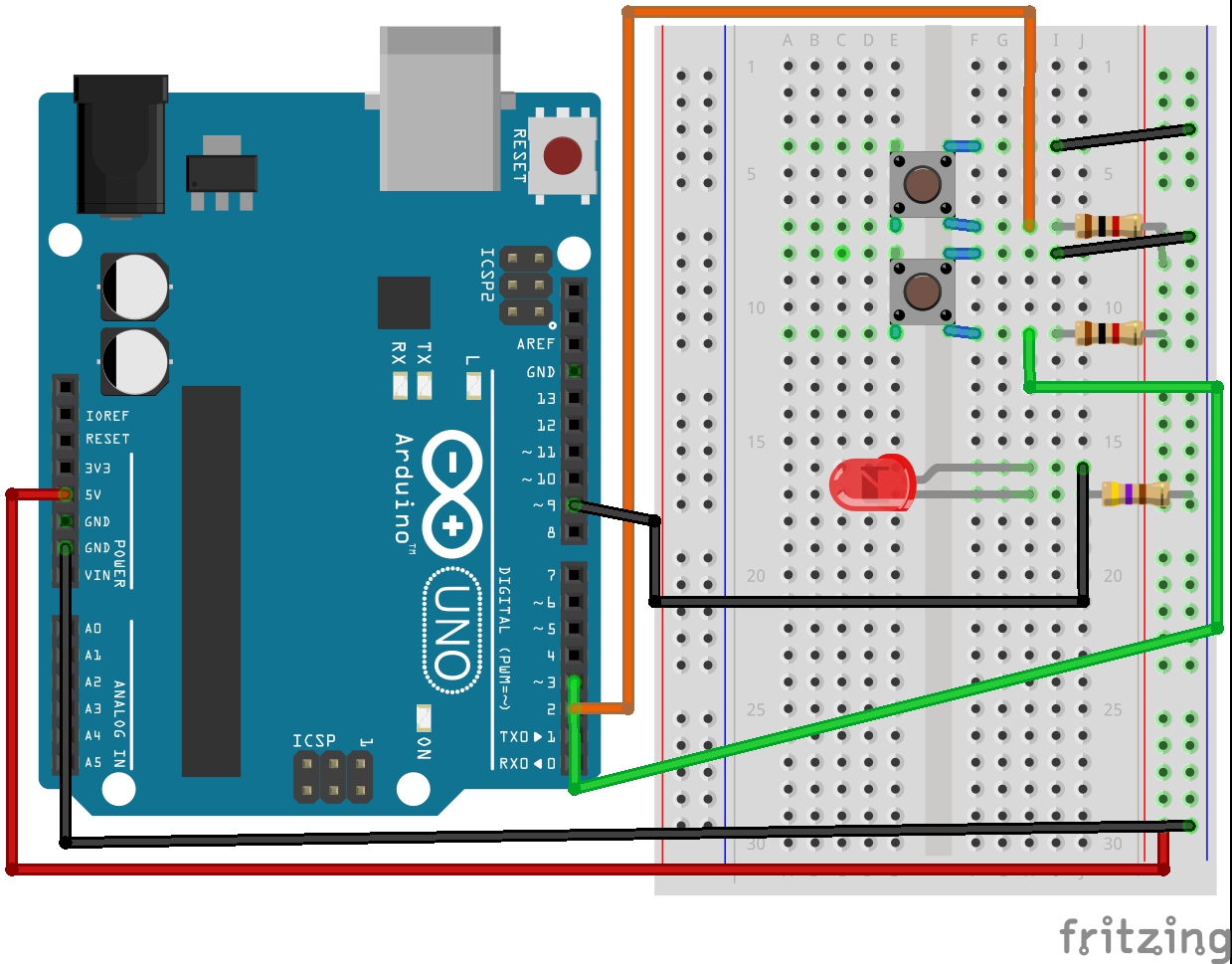
Fritzing diagram:
The Code:
/*
/*
* Button
* by DojoDave <http://www.0j0.org>
*
* Turns on and off a light emitting diode(LED) connected to digital
* pin 13, when pressing a pushbutton attached to pin 7.
* http://www.arduino.cc/en/Tutorial/Button
*/
int ledPin = 13; // choose the pin for the LED
int inputPin = 2; // choose the input pin (for a pushbutton)
int val = 0; // variable for reading the pin status
void setup() {
pinMode(ledPin, OUTPUT); // declare LED as output
pinMode(inputPin, INPUT); // declare pushbutton as input
}
void loop(){
val = digitalRead(inputPin); // read input value
if (val == HIGH) { // check if the input is HIGH
digitalWrite(ledPin, LOW); // turn LED OFF
} else {
digitalWrite(ledPin, HIGH); // turn LED ON
}
}


// //comment out the previous code and uncomment this for the second part

//int ledPin = 13; // choose the pin for the LED
//int inputPin1 = 3; // button 1
//int inputPin2 = 2; // button 2

//void setup() {
//  pinMode(ledPin, OUTPUT); // declare LED as output
//  pinMode(inputPin1, INPUT); // make button 1 an input
// pinMode(inputPin2, INPUT); // make button 2 an input
//}

//void loop(){

// if (digitalRead(inputPin1) == LOW) {
//    digitalWrite(ledPin, LOW); // turn LED OFF
// } else if (digitalRead(inputPin2) == LOW) {
//    digitalWrite(ledPin, HIGH); // turn LED ON /

////for part three comment the entire loop function and uncomment this , and then //change the input pin from 13 to 9

////int value = 0;
////void loop(){
//// if (digitalRead(inputPin1) == LOW) { value--; }
////  else if (digitalRead(inputPin2) == LOW) { value++; }
////  value = constrain(value, 0, 255);
////  analogWrite(ledPin, value);
////  delay(10);
////}

//  }
//}
  Button

 Turns on and off a light emitting diode(LED) connected to digital
 pin 13, when pressing a pushbutton attached to pin 7.


 The circuit:
 * LED attached from pin 13 to ground
 * pushbutton attached to pin 2 from +5V
 * 10K resistor attached to pin 2 from ground

 * Note: on most Arduinos there is already an LED on the board
 attached to pin 13.


 created 2005
 by DojoDave
 modified 17 Jun 2009
 by Tom Igoe

  http://www.arduino.cc/en/Tutorial/Button
 */

// constants won't change. They're used here to
// set pin numbers:
const int buttonPin = 2;     // the number of the pushbutton pin
const int ledPin =  13;      // the number of the LED pin

// variables will change:
int buttonState = 0;         // variable for reading the pushbutton status

void setup() {
  // initialize the LED pin as an output:
  pinMode(ledPin, OUTPUT);
  // initialize the pushbutton pin as an input:
  pinMode(buttonPin, INPUT);
}

void loop(){
  // read the state of the pushbutton value:
  buttonState = digitalRead(buttonPin);

  // check if the pushbutton is pressed.
  // if it is, the buttonState is HIGH:
  if (buttonState == HIGH) {
    // turn LED on:
    digitalWrite(ledPin, HIGH);
  }
  else {
    // turn LED off:
    digitalWrite(ledPin, LOW);
  }
}
int ledPin = 13; // choose the pin for the LED
int inputPin1 = 3; // button 1
int inputPin2 = 2; // button 2

void setup() {
  pinMode(ledPin, OUTPUT); // declare LED as output
  pinMode(inputPin1, INPUT); // make button 1 an input
  pinMode(inputPin2, INPUT); // make button 2 an input
}

void loop(){
  if (digitalRead(inputPin1) == LOW) {
    digitalWrite(ledPin, LOW); // turn LED OFF
  } else if (digitalRead(inputPin2) == LOW) {
    digitalWrite(ledPin, HIGH); // turn LED ON
  }
}
These assignments are due next Wednesday, October 29th.
We begin with three or four straightforward tutorials on sensors, and then make a creative assignment. (You can probably complete the sensor tutorials during class.)
Assignment-10A: PushButtons (Circuit 07)
Connect CIRC07 (Pushbuttons), on page 20 of the ARDX booklet.
Document the project in a blog post with a video, Fritzing diagram, and source code.
(Optional) Thoughts, observations or questions? Blog them too.
Connect CIRC08 (Twisting), on page 22 of the ARDX booklet. Take a photo or video, and then,
After this,
Connect CIRC13 (Squeezing), on page 32 of the ARDX booklet. It’s almost identical to CIRC08, which you just did.
Document the project(s) in a blog post with a video, Fritzing diagram, and source code.
(Optional) Thoughts, observations or questions? Blog them too.
Assignment-10C: Temperature (Circuit 10) + Serial
Connect CIRC07 (Pushbuttons), on page 20 of the ARDX booklet.
Note that the temperature sensor looks alot like the transistor! The temperature sensor is marked TMP36.
Also note that the temperature sensor is polarized, so make sure it’s inserted correctly. Otherwise you could get burned!
Try adding serial communication so that the temperature value is reported back to your laptop or desktop computer.
Document the project in a blog post with a video, Fritzing diagram, and source code.
(Optional) Thoughts, observations or questions? Blog them too.
Assignment 10-SensorDisplay
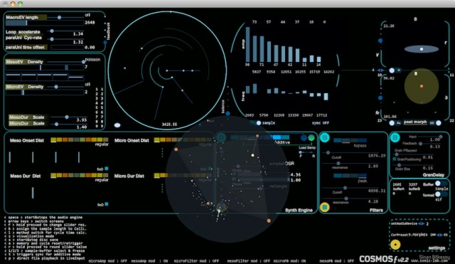
Create an interactive screen display in Processing that responds to one or more sensors, whose data is obtained from the Arduino over serial communications. For example, you might start from one of the following concepts (others are possible, too):
An interactive game which is played with a button, slider, force sensor, etc. (Consider how even a single button can be used to create a game like Flappy Bird.)
A dynamic abstraction or “interactive painting” whose properties change when the user turns some knobs — or which changes autonomously, according (for example) to the current temperature and ambient lighting conditions.
An information visualization which displays the diagnostic status of some sensor values (like an accelerometer), indicating movements in the world.
In creating your assignment, consider the following:
Nothing too fancy, but it might be nice to build a little cardboard box to hold your components.
You might need to extend your wires using solder.
Feel free to design a prototype which serves as a maquette or scale model for a much larger scenario. For example, you could pretend that the FSR in your kit actually represents an enormous pressure pad for detecting foot traffic .
Optionally, it can be Halloween related.
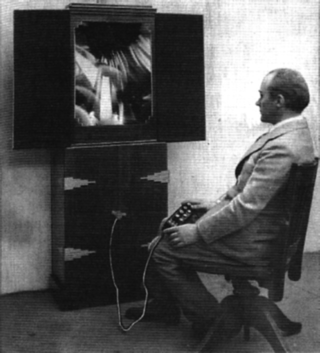
(Thomas Wilfred’s Clavilux (~1920) controlled a dynamic light abstraction from a set of potentiometers.)
A blog post, categorized Assignment-10-SensorDisplay
A short statement of 100-150 words describing your concept, process, and evaluation of your work
An embedded YouTube video demonstrating your project working
A scan of any paper sketches you made
A photograph of your project, perhaps in use
Some screenshots from your Processing display
A Fritzing diagram of your Arduino circuit
Your Arduino and Processing code, embedded using WP-Syntax
Here’s some Arduino and Processing code to get you started. The Arduino communicates serial data for two sensors to the Processing project, which parses the data and then displays the results.
Arduino code (v. 1.0.6):
// This Arduino program reads two analog signals,
// such as from two potentiometers, and transmits
// the digitized values over serial communication.

int sensorValue0 = 0;  // variable to store the value coming from the sensor
int sensorValue1 = 0;  // variable to store the value coming from the other sensor

void setup() {
  Serial.begin(9600);  // initialize serial communications
}

void loop() {

  // Read the value from the sensor(s):
  sensorValue0 = analogRead (A0);  // reads value from Analog input 0
  sensorValue1 = analogRead (A1);  // reads value from Analog input 1

  Serial.print ("A");
  Serial.println (sensorValue0);
  Serial.print ("B");
  Serial.println (sensorValue1);

  delay (50);   // wait a fraction of a second, to be polite
}

/*
The resulting serial data looks like this (for example):

A903
B412
A900
B409
A898
B406
A895
B404
A893
B404
...etcetera.
*/
Processing code (v. 2.2.1):
// This Processing program reads serial data for two sensors,
// presumably digitized by and transmitted from an Arduino.
// It displays two rectangles whose widths are proportional
// to the values 0-1023 received from the Arduino.

// Import the Serial library and create a Serial port handler
import processing.serial.*;
Serial myPort;

// Hey you! Use these variables to do something interesting.
// If you captured them with analog sensors on the arduino,
// They're probably in the range from 0 ... 1023:
int valueA;  // Sensor Value A
int valueB;  // Sensor Value B

//------------------------------------
void setup() {
  size(1024, 200);

  // List my available serial ports
  int nPorts = Serial.list().length;
  for (int i=0; i < nPorts; i++) {
    println("Port " + i + ": " + Serial.list()[i]);
  }

  // Choose which serial port to fetch data from.
  // IMPORTANT: This depends on your computer!!!
  // Read the list of ports printed by the code above,
  // and try choosing the one like /dev/cu.usbmodem1411
  // On my laptop, I'm using port #4, but yours may differ.
  String portName = Serial.list()[4];
  myPort = new Serial(this, portName, 9600);
  serialChars = new ArrayList();
}

//------------------------------------
void draw() {

  // Process the serial data. This acquires freshest values.
  processSerial();

  background (150);

  // draw a pink rectangle displaying valueA:
  fill (255, 200, 200);
  rect (0, 0, valueA, 100);

  // draw a blue rectangle displaying valueB:
  fill (200, 200, 255);
  rect (0, 100, valueB, 100);
  fill (0);

  // draw the letters A and B:
  text ("A", 20, 60);
  text ("B", 20, 160);
}


//---------------------------------------------------------------
// The processSerial() function acquires serial data byte-by-byte,
// as it is received, and when it is properly captured, modifies
// the appropriate global variable.
// You won't have to change anything unless you want to add additional sensors.

/*
The (expected) received serial data should look something like this:

 A903
 B412
 A900
 B409
 A898
 B406
 A895
 B404
 A893
 B404
 ...etcetera.
 */

ArrayList serialChars;      // Temporary storage for received serial data
int whichValueToAccum = 0;  // Which piece of data am I currently collecting?
boolean bJustBuilt = false; // Did I just finish collecting a datum?

void processSerial() {

  while (myPort.available () > 0) {
    char aChar = (char) myPort.read();

    // You'll need to add a block like one of these
    // if you want to add a 3rd sensor:
    if (aChar == 'A') {
      bJustBuilt = false;
      whichValueToAccum = 0;
    } else if (aChar == 'B') {
      bJustBuilt = false;
      whichValueToAccum = 1;
    } else if (((aChar == 13) || (aChar == 10)) && (!bJustBuilt)) {
      // If we just received a return or newline character, build the number:
      int accum = 0;
      int nChars = serialChars.size();
      for (int i=0; i < nChars; i++) {
        int n = (nChars - i) - 1;
        int aDigit = ((Integer)(serialChars.get(i))).intValue();
        accum += aDigit * (int)(pow(10, n));
      }

      // Set the global variable to the number we captured.
      // You'll need to add another block like one of these
      // if you want to add a 3rd sensor:
      if (whichValueToAccum == 0) {
        valueA = accum;
        // println ("A = " + valueA);
      } else if (whichValueToAccum == 1) {
        valueB = accum;
        // println ("B = " + valueB);
      }

      // Now clear the accumulator
      serialChars.clear();
      bJustBuilt = true;

    } else if ((aChar >= 48) && (aChar < = 57)) {
      // If the char is between '0' and '9', save it.
      int aDigit = (int)(aChar - '0');
      serialChars.add(aDigit);
    }
  }
}


 (Thomas Wilfred’s Clavilux (~1920) controlled a dynamic light abstraction from a set of potentiometers.)