Category: Assignment-09-PhotoresistorDocumented

Photoresistor

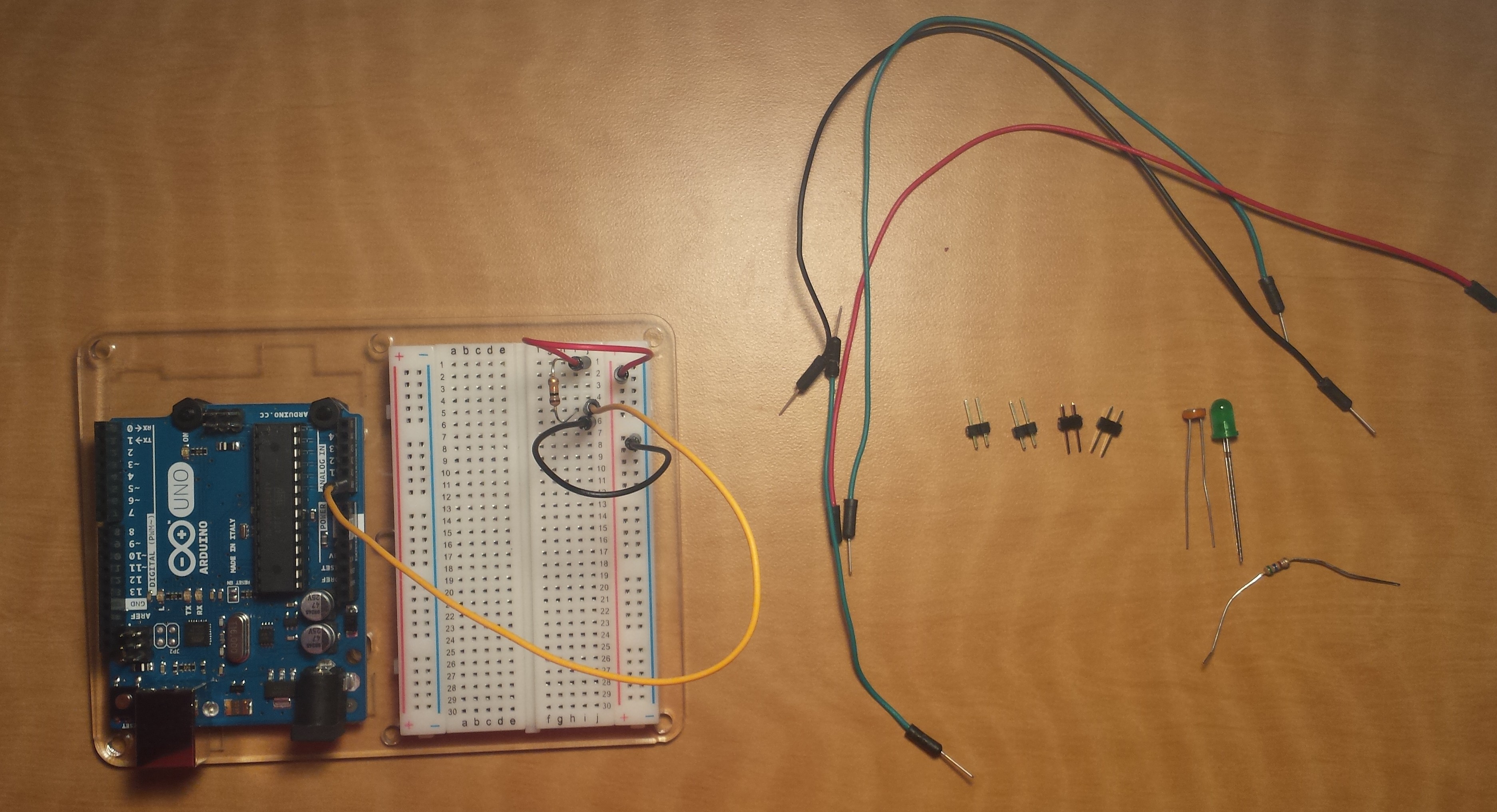
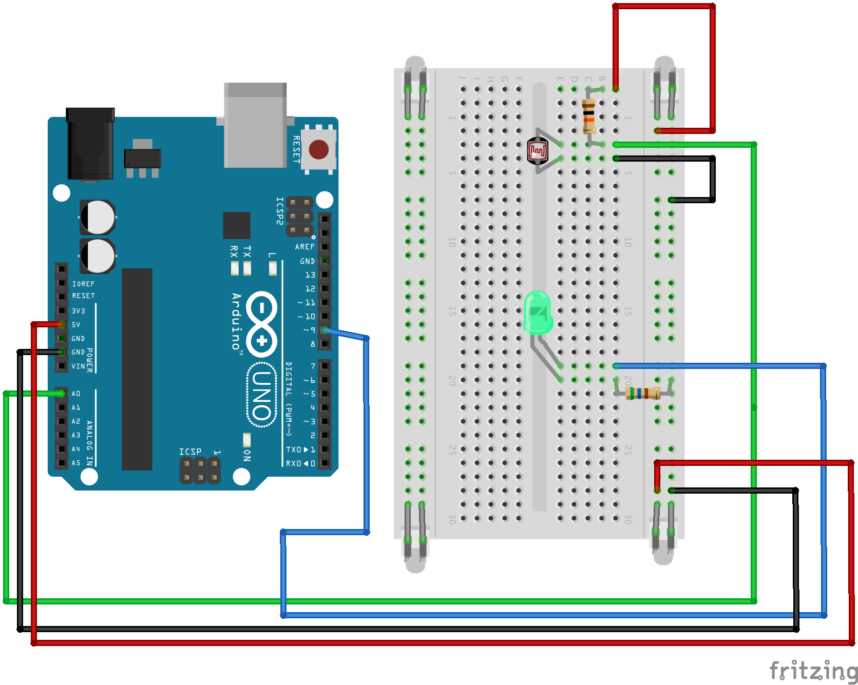
So I put together my circuit:

circuti

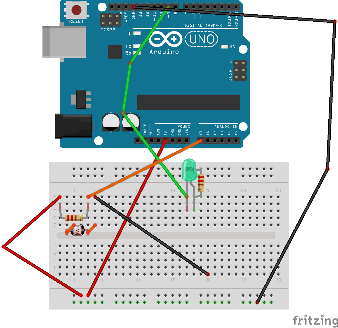
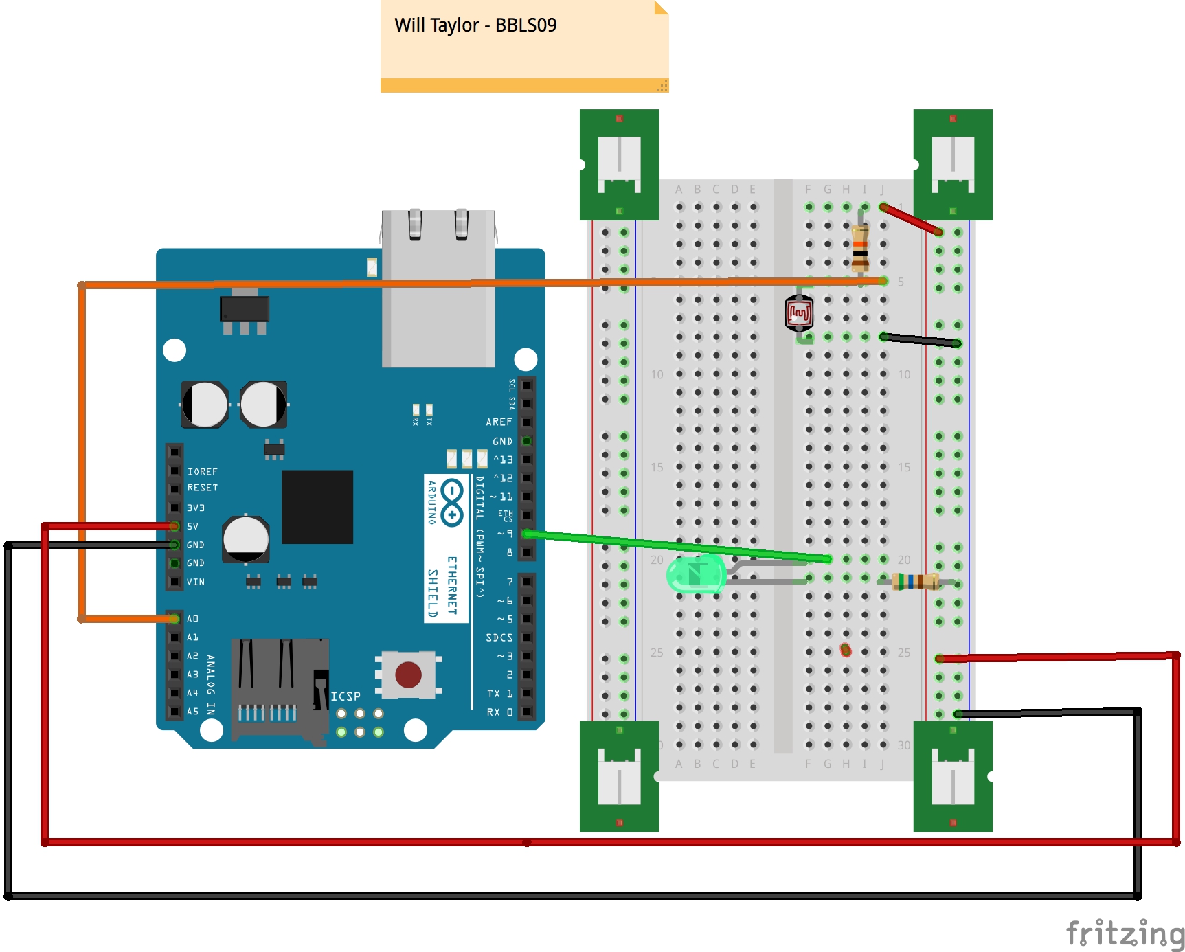
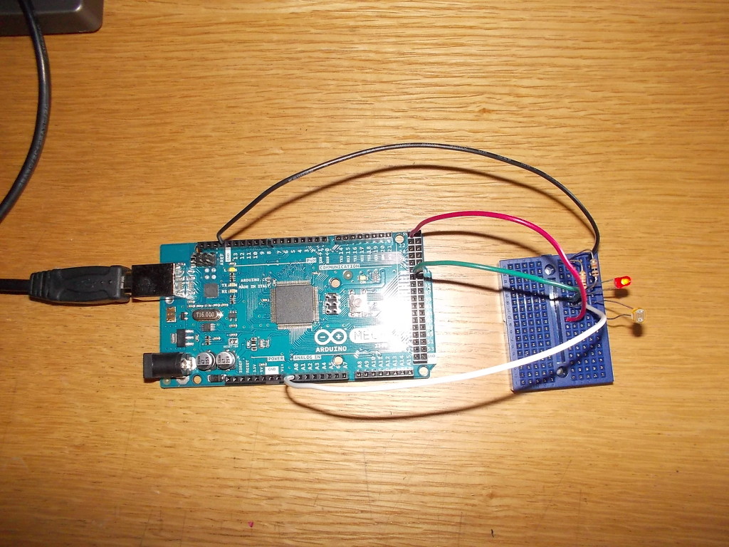
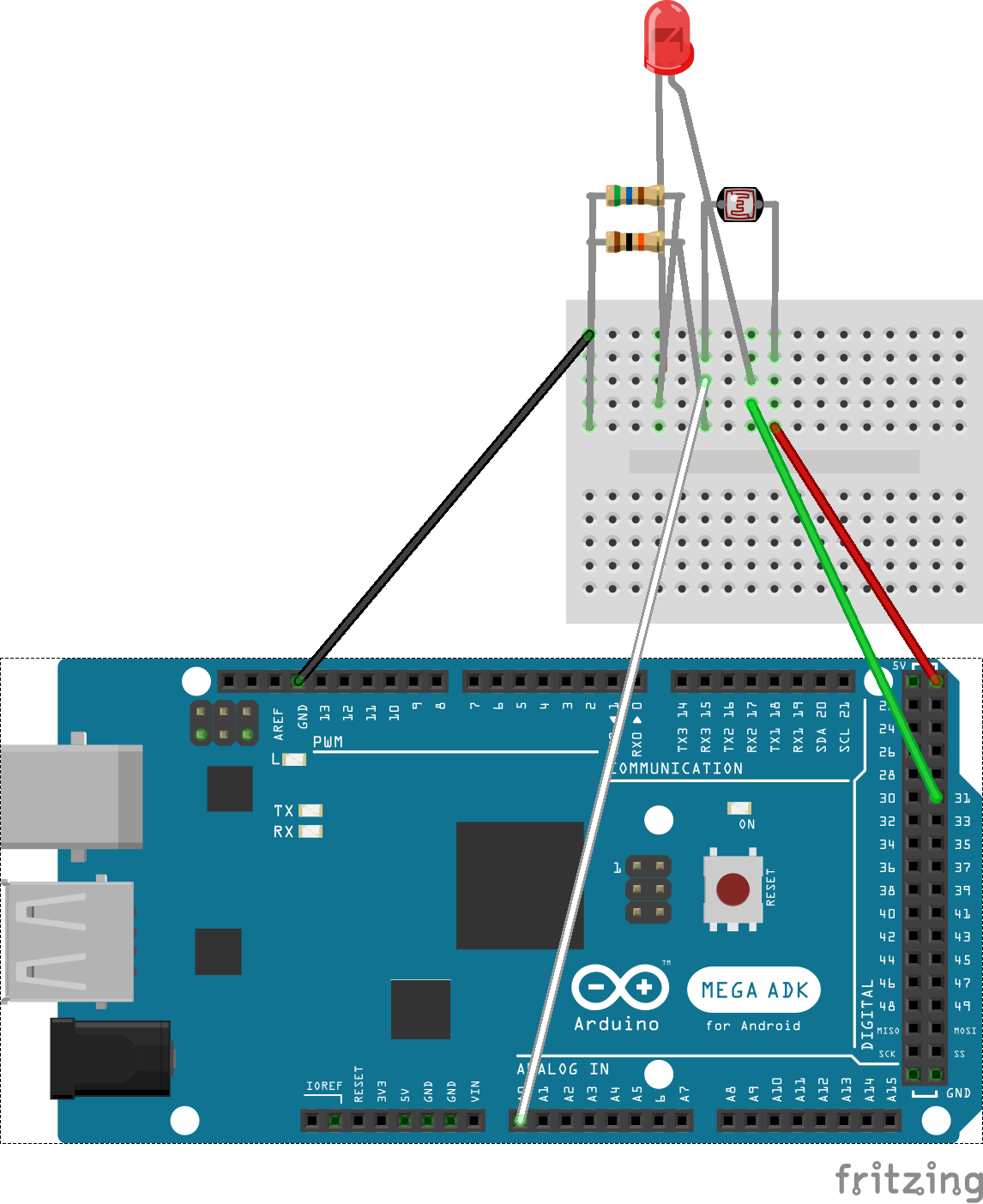
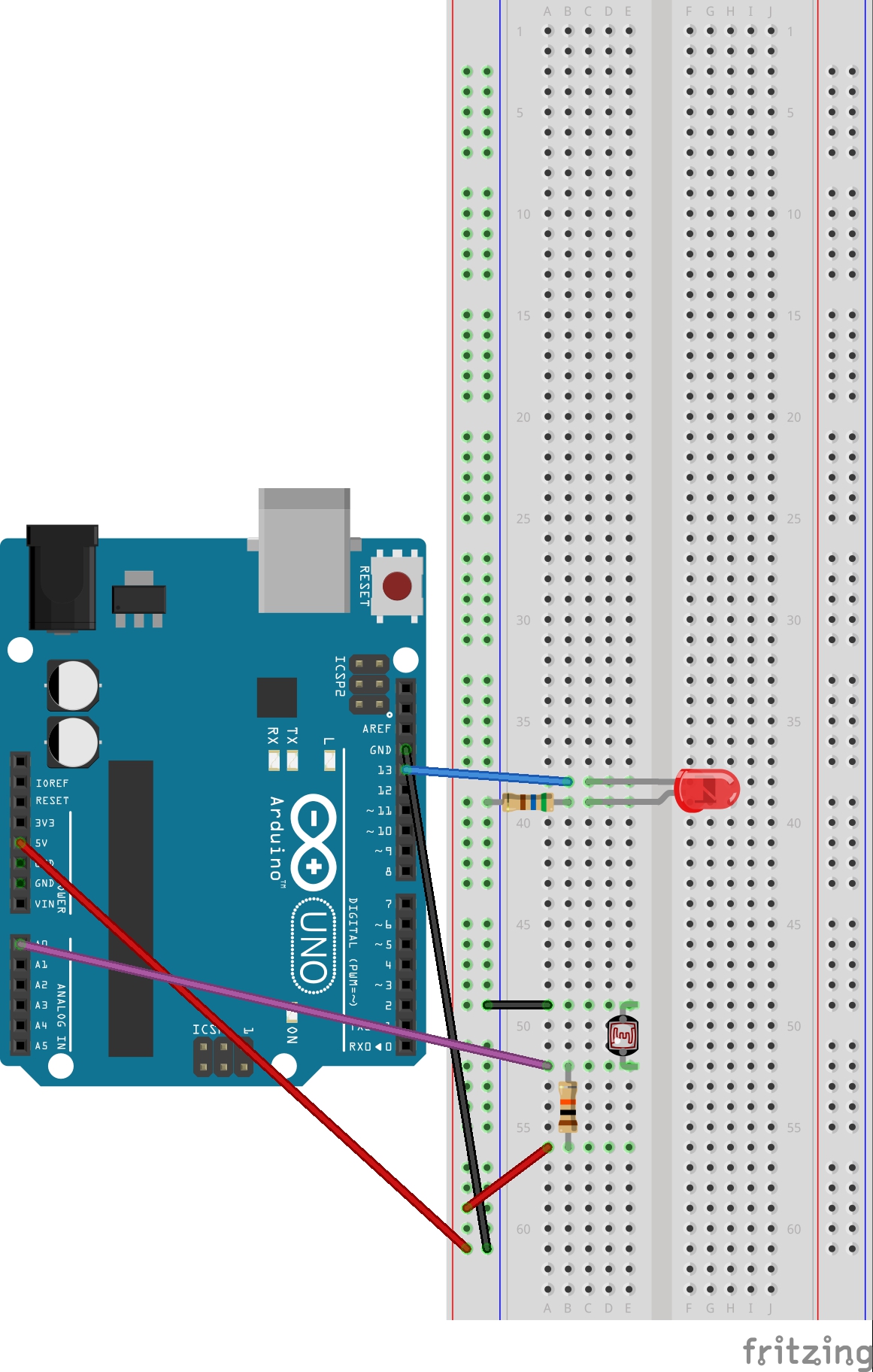
Displayed here in Fritzing form:

photores

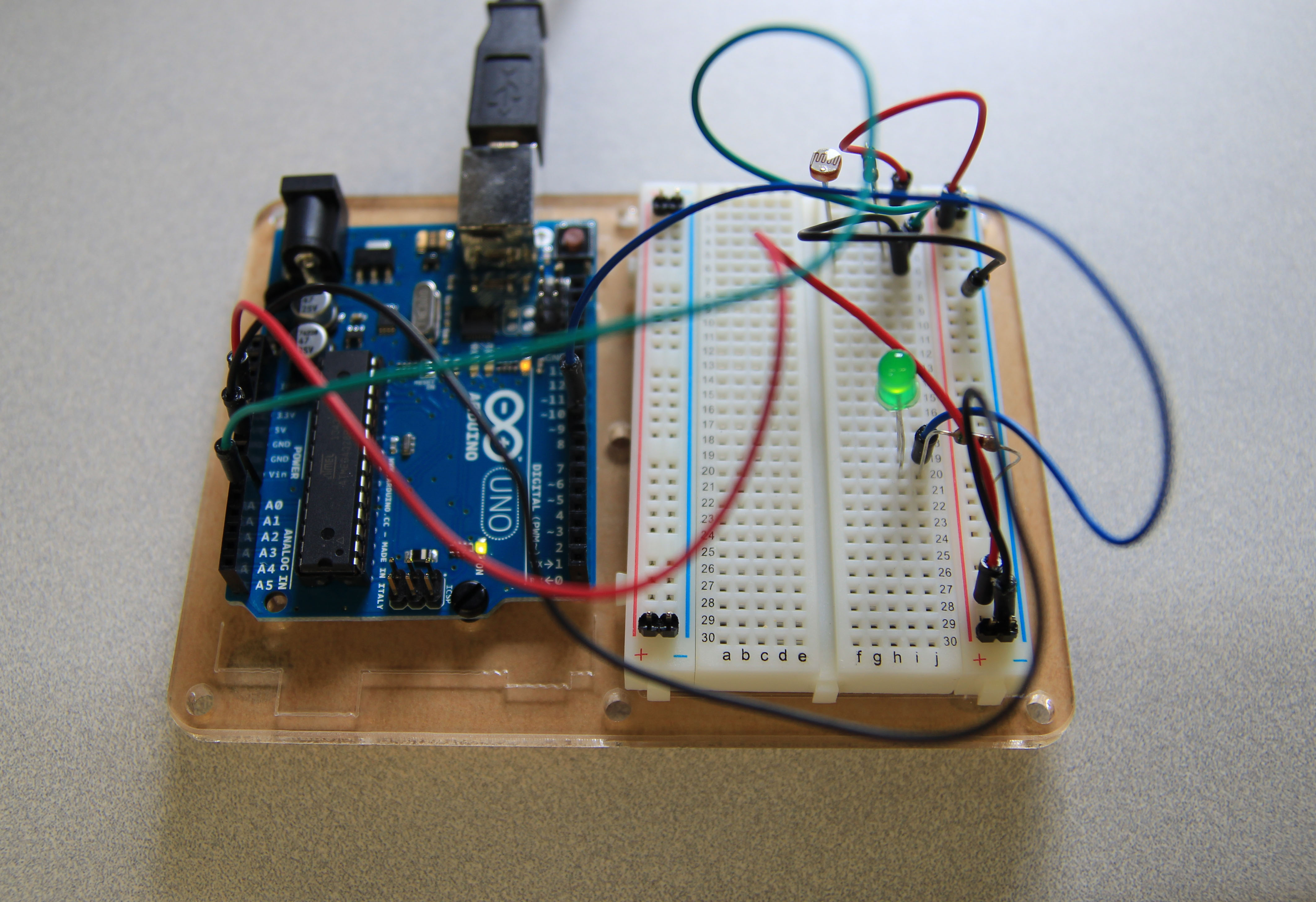
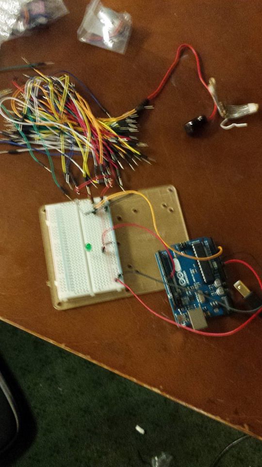
Miraculously, I found a way to make it work:

I need to get back into the swing of Arduino… :/

Code:

/*
 * A simple programme that will change the intensity of
 * an LED based  * on the amount of light incident on 
 * the photo resistor.
 * 
 */

//PhotoResistor Pin
int lightPin = 0; //the analog pin the photoresistor is 
                  //connected to
                  //the photoresistor is not calibrated to any units so
                  //this is simply a raw sensor value (relative light)
//LED Pin
int ledPin = 9;   //the pin the LED is connected to
                  //we are controlling brightness so 
                  //we use one of the PWM (pulse width
                  // modulation pins)
void setup()
{
  pinMode(ledPin, OUTPUT); //sets the led pin to output
}
 /*
 * loop() - this function will start after setup 
 * finishes and then repeat
 */
void loop()
{
 int lightLevel = analogRead(lightPin); //Read the
                                        // lightlevel
 lightLevel = map(lightLevel, 0, 900, 0, 255); 
         //adjust the value 0 to 900 to
         //span 0 to 255


 lightLevel = constrain(lightLevel, 0, 255);//make sure the 
                                           //value is between 
                                           //0 and 255
 analogWrite(ledPin, lightLevel);  //write the value
}

9 Photoresistor

My Photoresister experiment:

Setting Up

Setting Up

Parts:

CIRC-09 Breadboard Sheet

2 Pin Header

Photo-Resistor

Ohm Resistor Brown-Black-Orange

560 Ohm Resistor Green-Blue-Brown

Green LED

Fully functional

Fully functional


Fritzing Sketch:

project 9 sketch_bb2

Project Working on Video:

Project 9 from Elizabeth Agyemang on Vimeo.


Source Code:

/*
* A simple programme that will change the intensity of
* an LED based  * on the amount of light incident on
* the photo resistor.
*
*/

//PhotoResistor Pin
int lightPin = 0; //the analog pin the photoresistor is
//connected to
//the photoresistor is not calibrated to any units so
//this is simply a raw sensor value (relative light)
//LED Pin
int ledPin = 9;   //the pin the LED is connected to
//we are controlling brightness so
//we use one of the PWM (pulse width
// modulation pins)
void setup()
{
pinMode(ledPin, OUTPUT); //sets the led pin to output
}
/*

* loop() - this function will start after setup
* finishes and then repeat
*/
void loop()
{
int lightLevel = analogRead(lightPin); //Read the
// lightlevel
lightLevel = map(lightLevel, 0, 900, 0, 255);
//adjust the value 0 to 900 to
//span 0 to 255


lightLevel = constrain(lightLevel, 0, 255);//make sure the
//value is betwween
//0 and 255
analogWrite(ledPin, lightLevel);  //write the value
}

WHT – Photoresistor Documentation


BBLS09 Fritz Diagram


BBLS09 Documentation


/* Will Taylor - S 09
*
* A simple programm that will change the intensity of
* an LED based * on the amount of light incident on
* the photo resistor.
*
*/

//PhotoResistor Pin
int lightPin = 0; //the analog pin the photoresistor is
//connected to
//the photoresistor is not calibrated to any units so
//this is simply a raw sensor value (relative light)
//LED Pin
int ledPin = 9; //the pin the LED is connected to
//we are controlling brightness so
//we use one of the PWM (pulse width
// modulation pins)
void setup()
{
pinMode(ledPin, OUTPUT); //sets the led pin to output
}
/*
* loop() - this function will start after setup
* finishes and then repeat
*/
void loop()
{
int lightLevel = analogRead(lightPin); //Read the
// lightlevel
lightLevel = map(lightLevel, 0, 900, 0, 255);
//adjust the value 0 to 900 to
//span 0 to 255

lightLevel = constrain(lightLevel, 0, 255);//make sure the
//value is betwween
//0 and 255
analogWrite(ledPin, lightLevel); //write the value
}


Circuit 9 from Outer Space: Photoresistor Documentation

Building things is fun!

CIRC_9_FullRezolutionI found it useful that the instructions for building CRIC-9 (the photoresistor) showed multiple views of the components’ place on the breadboard. I now understand why each of the columns and rows have their own designation. The only point of frustration was that the wires kept getting in the way of the smaller components, in both assembly and documentation. CIRC9 Fritzing Diagram_bbAs for the Fritzing diagram, I’m not entirely sure if I used the proper object for the two-pin headers (and I’m still not entirely sure what they do), but the process of creating the diagram is straightforward, if a bit tedious.

/*
 * A simple programme that will change the intensity of
 * an LED based  * on the amount of light incident on 
 * the photo resistor.
 * 
 */

//PhotoResistor Pin
int lightPin = 0; //the analog pin the photoresistor is 
                  //connected to
                  //the photoresistor is not calibrated to any units so
                  //this is simply a raw sensor value (relative light)
//LED Pin
int ledPin = 9;   //the pin the LED is connected to
                  //we are controlling brightness so 
                  //we use one of the PWM (pulse width
                  // modulation pins)
void setup()
{
  pinMode(ledPin, OUTPUT); //sets the led pin to output
}
 /*
 * loop() - this function will start after setup 
 * finishes and then repeat
 */
void loop()
{
 int lightLevel = analogRead(lightPin); //Read the
                                        // lightlevel
 lightLevel = map(lightLevel, 0, 900, 0, 255); 
         //adjust the value 0 to 900 to
         //span 0 to 255


 lightLevel = constrain(lightLevel, 0, 255);//make sure the 
                                           //value is betwween 
                                           //0 and 255
 analogWrite(ledPin, lightLevel);  //write the value
}

Assignment 9 – Testing out a Light Sensitive Resistor

photoresistorled

assignment9circuit9

/*
 * A simple programme that will change the intensity of
 * an LED based  * on the amount of light incident on 
 * the photo resistor.
 * From ARDX Tutorial Circuit and Arduino Code
 */

//PhotoResistor Pin
int lightPin = 0; //the analog pin the photoresistor is 
                  //connected to
                  //the photoresistor is not calibrated to any units so
                  //this is simply a raw sensor value (relative light)
//LED Pin
int ledPin = 31;   //the pin the LED is connected to
                  //we are controlling brightness so 
                  //we use one of the PWM (pulse width
                  // modulation pins)
void setup()
{
  pinMode(ledPin, OUTPUT); //sets the led pin to output
}
 /*
 * loop() - this function will start after setup 
 * finishes and then repeat
 */
void loop()
{
 int lightLevel = analogRead(lightPin); //Read the
                                        // lightlevel
 lightLevel = map(lightLevel, 0, 900, 0, 255); 
         //adjust the value 0 to 900 to
         //span 0 to 255


 lightLevel = constrain(lightLevel, 0, 255);//make sure the 
                                           //value is between 
                                           //0 and 255
 analogWrite(ledPin, lightLevel);  //write the value
}